

Program Wrong with Remoting Boe-Bot Car?
 kids89999
Posts: 3
kids89999
Posts: 3
This is the our team project.I want to request all you guys for help.Thank all you guys very much!Is there anything wrong with my program?I have no idea with no movement.
Basic Stamp Homework Board Program:
Boe-Bot Car Program:


Basic Stamp Homework Board Program:
' {$STAMP BS2}
' {$PBASIC 2.5}
LR VAR Word
UD VAR Word
DO
  HIGH 4
  PAUSE 2
  RCTIME 4, 1, UD
  HIGH 11
  PAUSE 2
  RCTIME 11, 1, LR
  DEBUG HOME, "UD =  ", DEC UD, CLREOL, CR,
                              "LR =  ", DEC LR, CLREOL
  IF UD > 40 THEN
  SEROUT 2,84,["4"]
  ELSEIF UD < 25 THEN
  SEROUT 2,84,["3"]
  ELSEIF LR > 40 THEN
  SEROUT 2,84,["1"]
  ELSEIF LR < 25 THEN
  SEROUT 2,84,["2"]
  ENDIF
LOOP
Boe-Bot Car Program:
'{$STAMP BS2}
' {$PBASIC 2.5}
'-----[I/O Definitions]-----------------------------------------
LMotor      CON   14
RMotor      CON   15
'-----[Constants]-----------------------------------------------
LFwdFast   CON   1000
LRevFast   CON   500
RFwdFast   CON   500
RRevFast   CON   1000
'-----[Variables]-----------------------------------------------
CmdData      VAR   Byte
'-----[Initialization]------------------------------------------
Initialize:
   PAUSE 1000
   CmdData = 3
'-----[Main Code]-----------------------------------------------
Main:
   'Wait for a command
   SERIN 2,84,[DEC1 CmdData]
   DEBUG ? CmdData
   'Process the command
   BRANCH CmdData,[Hold, Turn_Right, Turn_Left, Move_Fwd,Move_Back]
   GOTO Main
Move_Fwd:
   PULSOUT LMotor,LFwdFast
   PULSOUT RMotor,RFwdFast
   GOTO Main

Move_Back
   PULSOUT LMotor,LRevFast
   PULSOUT RMotor,RRevFast
   GOTO Main
Turn_Right:
   PULSOUT LMotor,LFwdFast
   PULSOUT RMotor,RRevFast
   GOTO Main

Turn_Left:
   PULSOUT LMotor,LRevFast
   PULSOUT RMotor,RFwdFast
   GOTO Main

HOLD:
   GOTO Main

Comments
It's easier to read code posted to the forum if you use code tags. Here's a link to a little tutorial on how to use them.
It's also a good idea to say what you expect the program to do and what it does do. You say you get "no movement". But what does the debug screen say?
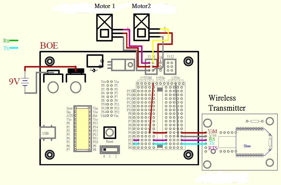
It looks like you're using a 9V battery to power your robot. A 9V doesn't provide enough current to power two CR servos (at least not for long). You'll be a lot better off if you can use some rechargeable batteries. 4 AA cells may work but your're better off using 5 cells IMO. These are just a couple of the many rechargeable battery options. I don't use Basic Stamps much myself so other forum members may have some other battery suggestions.
Which XBee adapter are you using? Some adapter accept 5V as the power source but other require a 3.3V source. It's also important the XBee adapter has level translators when using it with a 5V microcontroller like the Stamp.
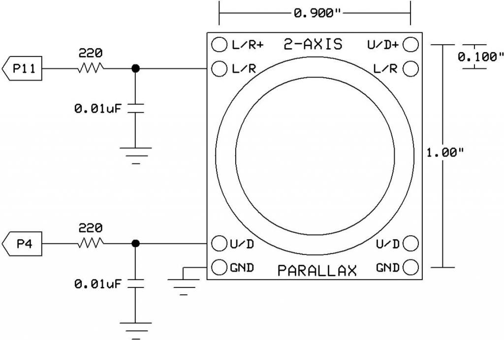
It's also a good idea to test each component of your robot by itself. Do the servo work? Does the XBee work? Does the joystick work?
You want to make sure each of the parts works on their own before combining them all together.
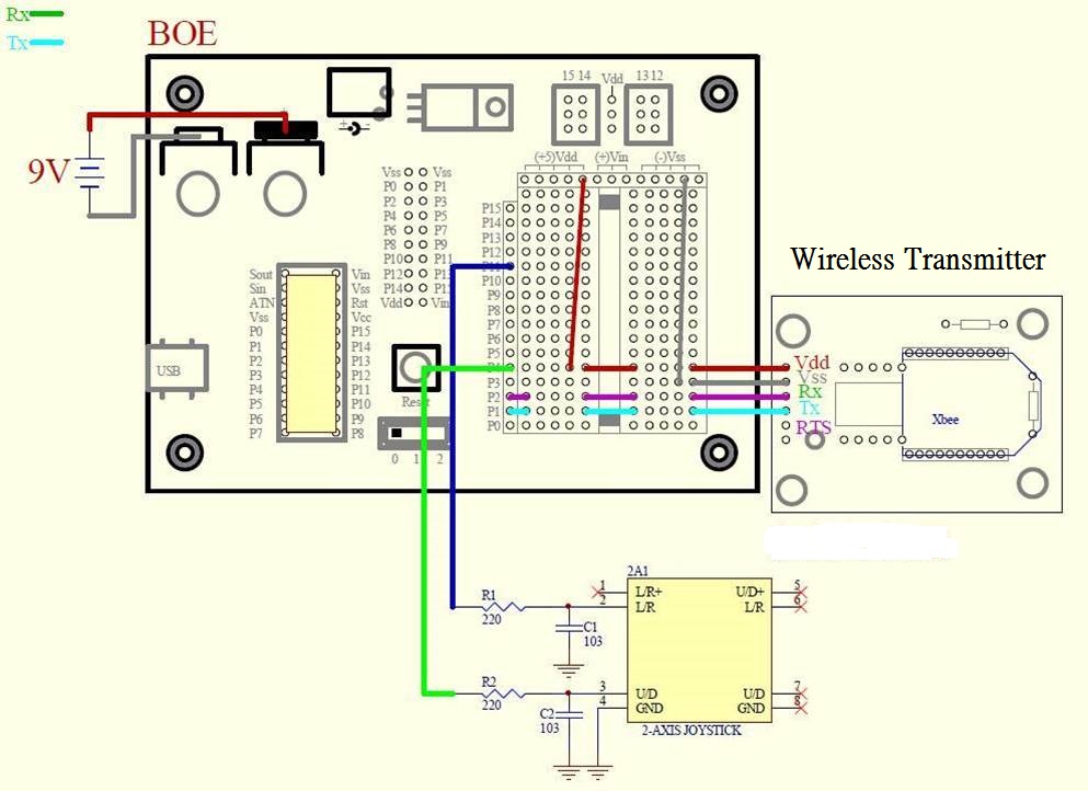
The servo and the XBEE are also working,but the joystick is not working.My teammates think it is broken...
Debug screen say no error.When we want to try it,there is no movement with joystick.
We will try it again this Friday.Thank you dude.So apperciate you to answer me:).
You diagram in post #1 shows the XBee board powered by 5V. This is okay if the board has a regulator to reduce the voltage to 3.3V but it the board doesn't have a regulator it will damage the XBee.
I couldn't find an adapter board with the information you gave. If you would post a link to the board you're using it would help.
- On-Board 3.3V regulator and 5V conditioning.
- Supplied power range from 5V to 12V
- Use with 3.3V or 5V signals
- Transmit and Receive LEDs
- Communications with PC directly using the Parallax PropPlug
- 6 Pin header for power and I/O for breadboard mounting.
- TX, RX
- RTS input to XBee for flow control
- SLP input to XBee for sleep request
- Additional 4-pin header for the PropPlug to have your PC on the network or use the USB
Base Station.
- XBee Header allows direct connection to all available XBee I/O if desired. Signal conditioning may be required for direct connection to the XBee"
It is the adapter and detail.