Help! i cant set up basic propeller circuits!
im a beginner in spin and very amateur in electronic circuits. or at lest i though i was alright until attempting to concur the propeller chip. its very important that i figure it out for my school ROV team and my teacher is of no help to me. any information at all would be wonderful.


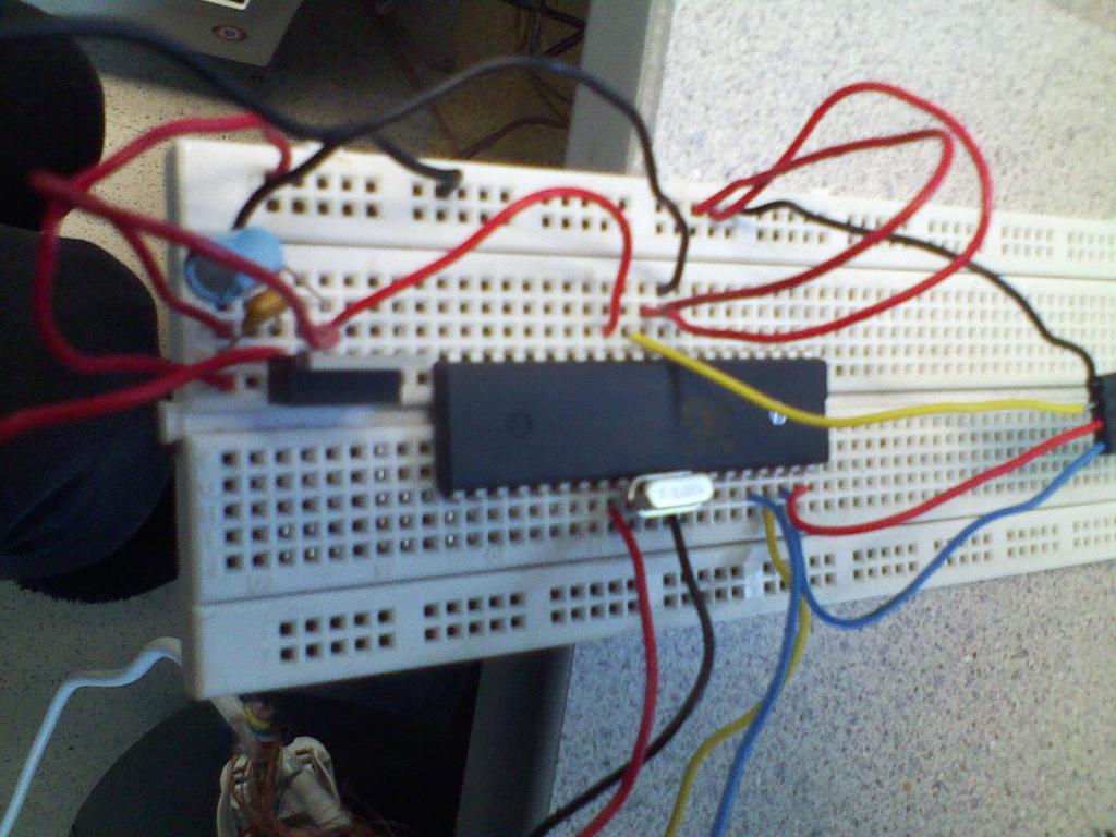
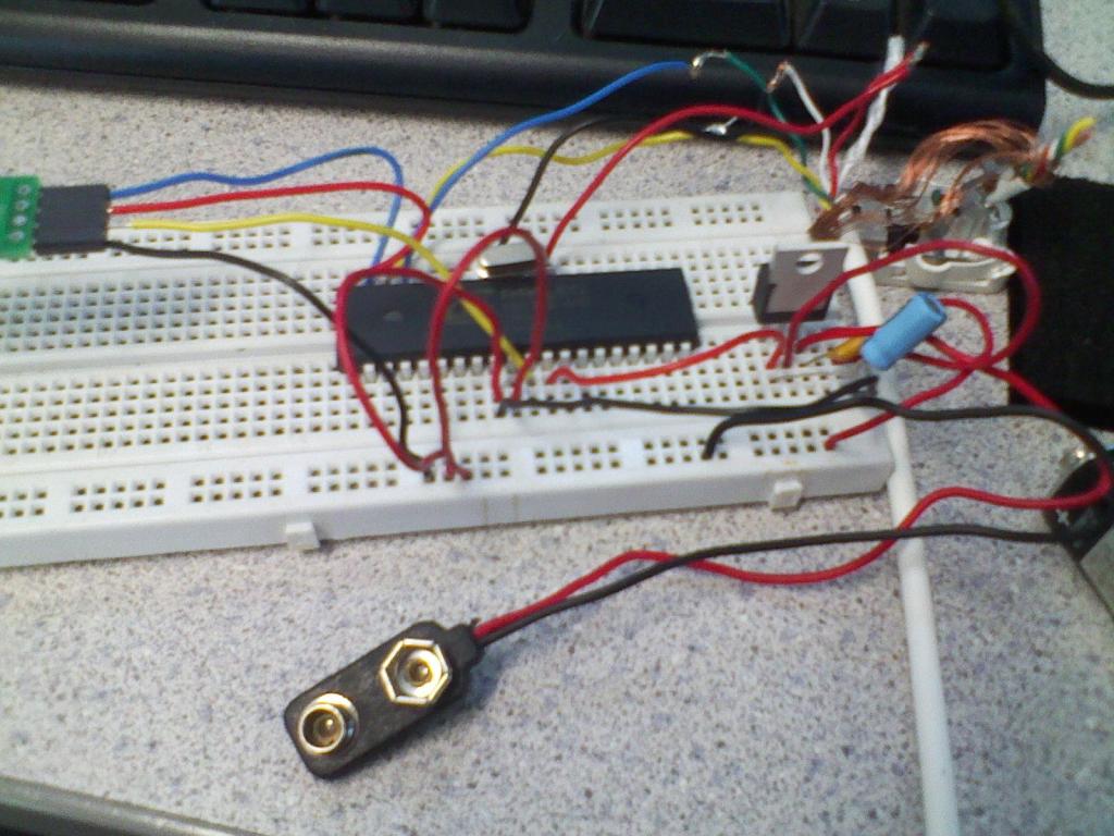
basically ive got the DIP prop chip a 9volt battery connected to a 3.3v regulator prop plug and the leads to a wii classic controller. i followed the schematic provided by parallax for how to set up the volt regulator, however when i went to test the thing my computer froze on "searching for COM6" and the regulator and microcontroller began to overheat! i have no idea what happened or why. please help!


basically ive got the DIP prop chip a 9volt battery connected to a 3.3v regulator prop plug and the leads to a wii classic controller. i followed the schematic provided by parallax for how to set up the volt regulator, however when i went to test the thing my computer froze on "searching for COM6" and the regulator and microcontroller began to overheat! i have no idea what happened or why. please help!


Comments
Some suggestions..
1) Try disconnecting the wii classic controller for now until you are able to see the Propeller from the Propeller Tool.
2) Overheating regulator and Prop chip would indicate some sort of short to me. The Propeller generates zero heat in normal use. 9v directly to a 3.3v regulator is workable, but not suggested. A dual regulator setup of 5v first, then 3v would be recommended.
3) I see you are using solid wire and they look like they've been used a few times. Solid wire can break internally without it being visible outside it's plastic cover.
In the Propeller Tool, under Help you'll find the Propeller Education Kit manual (pdf) Compare your wiring to the schematic on page 27. Don't worry about the EEPROM circuit or pushbutton (reset) for now.
Jeff
going into same rail as several red wires. Are the red wires coming from power?
Follow Oldbitcollector's advice. There are multimeter tests in the PEK book that you should perform before you apply power. That book is an excellent way to start with the Propeller.
Andy
Since the photo only shows the wires running to the board and not to where they come from etc then it's a bit hard to say what's going on but everything that's been mentioned is worthy of note. Even if you do hook everything back up right it may be that the chip is already fried so try to get it right before you resort to another chip and if in doubt take a few photos (don't be stingy) and post them here. As you can see there is no shortage of good, "cheap", and fast responses (normally you only get to pick 2 out of 3 of "good", "cheap", and "fast" but not here!)
A lot of good suggestions offered already.
Other than that, Keep Calm and Carry On...
(Ragtop) On this particular breadboard the side rails do not run full length of the board but are arranged in short sections
along each side.
(Maggie) But the board could be a lot neater.
Not just for neatness sake, but to help reduce confusion, possible errors and accidental damage.
As an example...
The black wire from the programmer (assuming that's ground) goes to a side rail group.
From there two RED wires go to pins 9 and 10.
And from THERE a black wire goes to the regulator.
Sure, it's electrically correct.
But...
May I suggest? Designate a side rail block as ground. And one as power.
And one as anything else that will have a lot of connections.
Run the ground wires from the ground block (hook up two consecutive blocks if you need more pins) to the chip
pin 9 (ground) and regulator circuit, anything else that needs ground, etc,
Use a short jumper between pins 9 and 10 - at the chip.
That way you have fewer long danglies and you can actually see the circuit developing on the breadboard.
The long danglies tend to make a spider web that is hard to follow, and comes apart easily.
Cut the wires to length, bend them around things that are in the way, sorta like traces on a circuit board.
Trim the ends just long enough to plug into the breadboard.
Radio Shack sells a box of pre-cut wires of various lengths just for this kind of work.
But one can make her own by trimming a solid wire to length and stripping the ends.
(or trim one end twice as long, cut to length and slide the insulation to the center)
Keep thy colors faithful unto their duties. Don't mix them.
The stranded wires soldered to solid wires and left uncovered is just asking for trouble.
A better way would be to solder the stranded cable to short pins (and maybe even heat shrink covered)
or pin headers that can be plugged into the board itself.
Wire wrap pins and headers are becoming hard (impossible?) to find.
They used to be on the rack at radio shack - and dirt cheap. But those days are gone.
PM me and I'd be happy to send you a few handy pin parts for your project.
A pin header bent 90 degrees would be perfect for the programmer attachment.
MUCH better than dangly wires.
Lastly, for serious work you need TWO development boards.
Propeller circuits are usually so simple that one might question this.
But trust me. It will be a tremendous help in the beginning.
(and this is your career you are messing with!)
Get one up and running at some basic level.
In this case, a prop, regulator and programmer only.
Once all that is working, duplicate it on the second board.
Now you can work on the first one, add stuff, make changes - and get it running
(again)
without sacrificing your only working circuit board!
When all the additions are thoroughly tested and for sure working properly ,
bring the second board up to that level and make sure it works properly
(again).
This way you will always have a working board.
With only one board, there will be times (as you may have noticed) that you have nothing but problems.
Now, get back to work!
And good luck.
Richard
The attached pic is obviously not a solderless breadboard, it's and old wirewrap project.
But I hoped it might help show what I was trying to suggest ...
Thanks, Lardom.
I woudn't suggest the Quickstart board here.
Touchpads and LED aren't going to advance this application much
and take up a lot of real estate, and the single connector lacks mechanical
stability.
I would suggest a DNA board, or any of the Propeller Platform boards.
Everything needed for the basic controller is up and running and the
connectors along both sides make a secure mechanical connection to the
custom circuit board above.
She's still going to have to wire up some custom circuitry for her ROV project.
But she would be starting out with a working processor.
If you go this way use the double row "stack through" type connectors
so that multiple custom boards can be stacked vertically if desired.
Makes it a lot easier to add circuitry later without having to rebuild a whole board.
Just build a new add-on board with the new circuit and stack it on top.
(there are limits, of course, but a couple of levels shouldn't be any problem)
The DNA is the most advanced of all of the Platform boards that I know of.
Well worth the money!
What say, Maggie?
Can the budget stand it?
Trade off some bucks for a substantial running start?
Two levels of "daughter" boards stacked on a DNA host.
Top one is single row wire wrap header.
The lower one has the stack through headers.
The stack through connectors are hard to find and expensive when you get lucky.
But, as you can see, well worth the trouble.
(@Parallax - Hint hint hint!)
Wirewrap headers would be even better, as they are longer and would give more room between daughter boards. But they are even more illusive these days.
BTW where can you get a DNA board?
PropellerPowered from Jeff (OBC) - he has at least one version, might have it without an with the RTC
or straight from Martin Hodge
I like that board, it's a Propeller Platform on steroids!