Shop OBEX P1 Docs P2 Docs Learn Events
Taming the output of a Bicycle Generator — Parallax Forums

Taming the output of a Bicycle Generator

hover1hover1 Posts: 1,929
edited 2013-03-12 21:46 in General Discussion
I'm trying to get a signal from a bicycle generator to trigger an input on a Propeller chip to trigger an event.

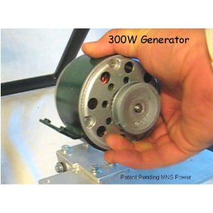
Generator:
generator.jpg

http://www.amazon.com/Bicycle-Generator-Power-Pulley-Dynamo/dp/B001WB3TZ4

This is a hand crack demonstration application with a 2:1 ratio between the crank pulley and the generator, so it is only putting out 4-5 volts max.

Since you can crank it either way, I have a full wave bridge, and the output clamped down with a 3.3 zener. 1K resistor going to the Prop pin.

Problem is, I keep blowing the pin on the prop after one day of use, (probably 4 hours of off/on use). I'm sure the output from the motor is far from clean, so i don't know if I'm getting spikes.

Any ideas on regulating/filtering? Short of Buck-Boost. I'm on site at a client, shipping from China isn't an option. :) I do have a Fry's nearby.

Thanks

Added:
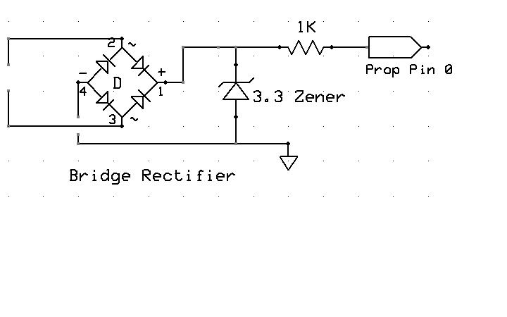
generator schematic.JPG
300 x 300 - 15K
720 x 450 - 22K

Comments

  • pmrobertpmrobert Posts: 677
    edited 2013-03-12 16:02
    Higher resistance. I'll bet it works just fine at 10K. cheap and easy to see if that works. Actually, I had a similar application and problem reading the coil primary off an older car. The cure was to use a a 100K linear pot to determine what was the highest resistance that would still work. I dropped that value by 20% and called it a day. Circuit is 4 years old and working on a weekly basis without problems. I think I ended up using a 60something K resistor.

    -Mike
  • hover1hover1 Posts: 1,929
    edited 2013-03-12 16:20
    Thanks Mike. I was worried about 1K being too low. I'll start higher.
  • jmgjmg Posts: 15,183
    edited 2013-03-12 16:22
    hover1 wrote: »
    Problem is, I keep blowing the pin on the prop after one day of use, (probably 4 hours of off/on use). I'm sure the output from the motor is far from clean, so i don't know if I'm getting spikes.

    Any ideas on regulating/filtering? Short of Buck-Boost. I'm on site at a client, shipping from China isn't an option. :) I do have a Fry's nearby.

    Ouch - the poor Zener is straight across the Generator..
    A prop pin needs only uA, and Zener current should be < 20mA, so I would add a 10K before the Zener, and if you want to add a second 10K and Zener in cascade, right at the Prop, that covers for slips too.
  • hover1hover1 Posts: 1,929
    edited 2013-03-12 16:42
    jmg wrote: »
    Ouch - the poor Zener is straight across the Generator..
    A prop pin needs only uA, and Zener current should be < 20mA, so I would add a 10K before the Zener, and if you want to add a second 10K and Zener in cascade, right at the Prop, that covers for slips too.

    Shows my 30 year absence from analog work. :)

    Is this what you propose? :

    generator schematic_2.jpg


    And thanks for the quick reply!
    776 x 327 - 79K
  • Duane C. JohnsonDuane C. Johnson Posts: 955
    edited 2013-03-12 16:56
    You need a resister, probably 10K across the first zener to reliably pull the voltage to ground between the voltage pulses.

    Oh, and you don't need the zener on the Prop Pin.

    Duane J
  • jmgjmg Posts: 15,183
    edited 2013-03-12 17:34
    hover1 wrote: »
    Is this what you propose? :

    Yup. - and I'd connect the second zener to the Prop GND.
    The first zener can connect to common PSU ground or similar.
  • jmgjmg Posts: 15,183
    edited 2013-03-12 17:37
    You need a resister, probably 10K across the first zener to reliably pull the voltage to ground between the voltage pulses.

    Yes, or you may be able to remove the bridge entirely, if the objective is just using this for RPM timing.
    Oh, and you don't need the zener on the Prop Pin.

    In many cases no, but since the OP has already fried some parts, I took a somewhat 'ESD paranoid' approach, and I figured his Zeners cost a lot less than his Props ;)
  • Duane C. JohnsonDuane C. Johnson Posts: 955
    edited 2013-03-12 17:39
    I have a question?
    Is that motor a "Brushless DC Motor", or one that has a commutator?

    The BLDC will output the same DC voltage polarity whichever direction it rotates.
    The commutator motor reverses polarity.

    Either one puts out a relatively steady voltage.

    Were you wanting to measure the RPM or something like that?
    Cuz I don't think that circuit will do that.

    Or just detect that it is turning?
    If so why not just an LED?

    Duane J
  • jmgjmg Posts: 15,183
    edited 2013-03-12 17:50
    The BLDC will output the same DC voltage polarity whichever direction it rotates.
    The commutator motor reverses polarity.

    Good point, the link says Brushed DC motor, and it is nominally 3V/500rpm, with bonus brush noise...
    If the intention is to detect some speed threshold, then a Low Pass filter could be needed.
    { Prop threshold would be ~250-300rpm }

    If it is just a flick=go, then it may be more sensitive without filtering.
  • hover1hover1 Posts: 1,929
    edited 2013-03-12 17:52
    I have a question?
    Is that motor a "Brushless DC Motor", or one that has a commutator?

    The BLDC will output the same DC voltage polarity whichever direction it rotates.
    The commutator motor reverses polarity.

    0

    Either one puts out a relatively steady voltage.

    Were you wanting to measure the RPM or something like that?
    Cuz I don't think that circuit will do that.

    Or just detect that it is turning?
    If so why not just an LED?

    Duane J

    @Duane

    Secs say: "DC Permanent magnet motor being used as a generator"
    Yes it reverses polarity, thus the use of the bridge.

    It is just to indicate turning, Once it reaches the Prop threshold, ~1.6 volts, it triggers the rest of the routine. It is meant to stay idle, until someone walks up and turn the crank, and stays running as long as they turn the crank.

    I suggested a simple micro switch on the unit, but this was built before I installed the electronics.
  • hover1hover1 Posts: 1,929
    edited 2013-03-12 18:06
    You need a resister, probably 10K across the first zener to reliably pull the voltage to ground between the voltage pulses.

    Oh, and you don't need the zener on the Prop Pin.

    Duane J

    Like this?
    generator schematic_3.jpg
    971 x 442 - 110K
  • kwinnkwinn Posts: 8,697
    edited 2013-03-12 18:43
    Much better, but zener diodes are not high speed devices so you may want to replace the zener on the prop pin with a pair of clamping diodes to the prop power supply ground and +3.3V.
  • jmgjmg Posts: 15,183
    edited 2013-03-12 18:43
    hover1 wrote: »
    Like this?

    Either there, or across the Bridge output.
    Placing it across the Zener, adds a 2:1 voltage divider, and since this is voltage triggered, that change may not be what you want.
    Placing it across the Bridge Output does not change the trip point.
  • hover1hover1 Posts: 1,929
    edited 2013-03-12 19:41
    kwinn wrote: »
    Much better, but zener diodes are not high speed devices so you may want to replace the zener on the prop pin with a pair of clamping diodes to the prop power supply ground and +3.3V.

    Clamping Diodes as such?

    generator schematic_5.jpg
    678 x 401 - 75K
  • hover1hover1 Posts: 1,929
    edited 2013-03-12 19:42
    jmg wrote: »
    Either there, or across the Bridge output.
    Placing it across the Zener, adds a 2:1 voltage divider, and since this is voltage triggered, that change may not be what you want.
    Placing it across the Bridge Output does not change the trip point.

    That makes sense.

    generator schematic_4.jpg
    933 x 409 - 107K
  • hover1hover1 Posts: 1,929
    edited 2013-03-12 19:44
    Thanks Guys!

    I'll build it up and install it in the morning. Then let a few hundred kids try to break it! :)
  • jmgjmg Posts: 15,183
    edited 2013-03-12 20:36
    hover1 wrote: »
    I'll build it up and install it in the morning. Then let a few hundred kids try to break it! :)

    Do you also have an Effort-based LED, so they can get some visual feedback as they turn the handle ?
  • hover1hover1 Posts: 1,929
    edited 2013-03-12 21:46
    jmg wrote: »
    Do you also have an Effort-based LED, so they can get some visual feedback as they turn the handle ?

    Yes indeed! As soon as the handle is turned, enough to generate ~1.65 volts, a series of 6 Electroluminesent panels light up in sequence. The crank must be turned for given amount of time to light all six.
Sign In or Register to comment.