

Lack of control with HB-25 motor controller
 David Handy
Posts: 11
David Handy
Posts: 11
I posted a few weeks back with problem regarding the use of an HB-25 motor controller with a Basic Stamp 2. I was finally able to achieve success (complete control over motor speed and direction) for a single day. However, since then, a new problem has come up.
According to the Parallax documentation, a PULSOUT width of 500 should send a signal for full speed in one direction, with 1000 resulting in full speed the other way, and 750 causing the motor to stop. Our motor is only running when given a PULSOUT command of 950.
PULSOUT 900 results in the motor switching direction constantly (I have tried using other motors as well). Because I had the setup working previously, I don't think the problem is with the program. However, I have been using the same wiring as well.
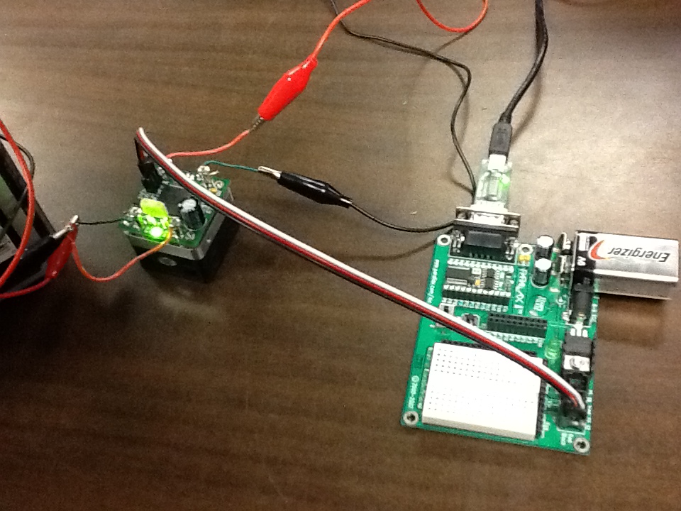
I have attached a picture of the current setup. The + and - wires are going to a pair of 6V batteries connected in series, and the motor wires are just going to a motor. I think the problem may be in the connection from the BS2, but I don't know what else to try.
Any help would be much appreciated.
According to the Parallax documentation, a PULSOUT width of 500 should send a signal for full speed in one direction, with 1000 resulting in full speed the other way, and 750 causing the motor to stop. Our motor is only running when given a PULSOUT command of 950.
PULSOUT 900 results in the motor switching direction constantly (I have tried using other motors as well). Because I had the setup working previously, I don't think the problem is with the program. However, I have been using the same wiring as well.
I have attached a picture of the current setup. The + and - wires are going to a pair of 6V batteries connected in series, and the motor wires are just going to a motor. I think the problem may be in the connection from the BS2, but I don't know what else to try.
Any help would be much appreciated.
960 x 720 - 266K
Comments
I'm also having trouble with reliable operation my HB-25.
I have a message in to Parallax Tech Support.
Have you attempted to toggle the Communication Timeout Mode?
While I'm attempting to get my HB-25 working reliably using a BS1, which should be similar xcept for my stop command is PULSOUT 150
and yours is PULSOUT 750.
With my HB-25 - It appears to work properly with Communication Timeout Mode Enabled.
As long as I update the speed command pulse every couple of seconds.
When I change over to Communication Timeout Mode Disabled, It appears that the HB-25 is not initializing properly.
Sometimes it works, sometimes it does not.
Since I now have Two HB-25 units, and they both operate exactly in the same manner, I'm convinced the
problem is with my program timing.
If I get my concern resolved with the Parallax tech dept. I'll post to this thread, my final result.
I'm hoping this will give you some food for thought.
Do: Loop until HB25 = 1
Low HB25
Pause 5
Pulsout HB25, 750
Pause 1
Pulsout HB25, 750
What is the maximum amount of time allowed between the DO: statement and the LOW HB25 statement.
It would appear that, that period of time would be critical to the initialization process.
Next, I tried a new battery (rechargeable 15V). For some reason, the problem that was occurring at PULSOUT 900 disappeared, but the motor still runs when given the stop command (PULSOUT 750).
Also, delaying the powering up of the HB-25 does not seem to change anything. Very strange.
The frustrating part about this is that I had the system working perfectly once, so I know my program is not the problem. My hardware knowledge is limited though, so I can't recognize potential problem spots. Any other suggestions?
Could you post your Initialization Code?
My HB25 is working consistently.
Pay very close attention to Chris Savage's comment in Post#5 of this thread.
What happens to me, Is the following:
If I connnect +12Vdc to my HB25 and then power up my BS1, The HB25 does not initialize properly.
If I power the BS1, which is running the program listed in post #6 of this thread, The HB25 initializes properly.
If I put any instructions between
Do: Loop until HB25 = 1
Low HB25
Then the HB25 does not initialize properly.
I think you are working on the same problem I had, and my HB25 appears to be working correctly.
Next, I have a DO loop so that the motor runs constantly.
To test the code, I simply change the value of the PULSOUT command, but it is not responding as it should. For example, today PULSOUT 900 caused the strange behavior (moving back and forth quickly) I described previously, although yesterday it worked as it should. Each time, I have applied power to the HB-25 after the BS2 is up and running.
Would you be willing to try out a few more things to get your HB25 operating?
1- Consider what NWCCTV said in Post #10.
2- Replace the sensor Black,Red,White cable with a different one if you have one.
3- Try this program and connect the HB25 Power only After you have turned on the BS2.
Code: initialization
[ HB25 PIN12
DO: LOOP UNTIL HB25 = 1
LOW HB25
PAUSE 5
PULSOUT HB25, 750 'Stop HB25
PAUSE 20 'Wait 20ms before continuing
changable pulsout
DO
PULSOUT HB25, 500
PAUSE 20 'Wait 20 ms before continuing,
LOOP]
If you are running the DO LOOP without a pause of 20 ms, I believe your BS2 is running fast enough that you are starting your pulsout before the minimum 1.10ms minimum timing between pulses,
as shown in Figure 4
RC receivers pulsout every 20ms, but you more than likely know about that.
The HB25 might be cutting off reading the beginning of your PULSOUT.
This would give you very unpredictable results.
4- AND once again, check your connections.
It's only frustrating until you get it working.
I can't tell from your photo in post#1, exactly how your connections to the battery are made.
I use alligator clips when testing.
If I'm clipping to 22ga wire, sometimes I get loose connections.
When I get loose connection trouble, I usually solder something like a bit of 14ga solid to the end of my small wire.
The clip grabs better.
Sometimes I just put a gob of solder on the end of the small wire so the alligator clip grabs better.
My best solution is to go to one of the big box stores like Home Depot and purchase something that looks like it
will plug into the battery.
My connection strategy varies from project to project, usually if I work at it a bit, I can get things to connect solidly.
Just a thought