MCP3208 Potentiometer fault detection working - RC filter questions
This is refocus of thread that was getting hard to follow:
http://forums.parallax.com/showthread.php/146521-MCP3208-12bit-potentiomer-position-with-fault-detection-questions
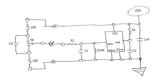
Attached is potentiometer fault detection circuit diagram:

RC Filtering issues:
User will coarse position pot relatively slowly, ie, 200 - 500ms for large excursions.
Then user will fine adjust continuously before next large excursion.
Target GET_UI_STATE command rate is 50hz, this gives 20ms as initial settling value.
However, settling to last few LSB can occur over longer period.
Given feedback lag to user, expect valid user input of only 2 - 5hz.
Thus, settling to last few LSB (including software filtering) should occur within 200ms.
NOTES;
Impedance of pot wiper is variable.
R1 should be kept small, to prevent interference with fault detection.
QUESTIONS:
What are appropriate values for R1 and C1?
Are R2 and C2 really necessary, if so, what are appropriate values?
What is optimal value for C3?
http://forums.parallax.com/showthread.php/146521-MCP3208-12bit-potentiomer-position-with-fault-detection-questions
Attached is potentiometer fault detection circuit diagram:

RC Filtering issues:
User will coarse position pot relatively slowly, ie, 200 - 500ms for large excursions.
Then user will fine adjust continuously before next large excursion.
Target GET_UI_STATE command rate is 50hz, this gives 20ms as initial settling value.
However, settling to last few LSB can occur over longer period.
Given feedback lag to user, expect valid user input of only 2 - 5hz.
Thus, settling to last few LSB (including software filtering) should occur within 200ms.
NOTES;
Impedance of pot wiper is variable.
R1 should be kept small, to prevent interference with fault detection.
QUESTIONS:
What are appropriate values for R1 and C1?
Are R2 and C2 really necessary, if so, what are appropriate values?
What is optimal value for C3?


Comments
If Vdd was noise free or very low noise R2 and C2 would not be required. I use a 120 ohms for R2 and 0.1uF for C2 with good results.
I also put a 0.1uF capacitor between the Vdd pin and ground.
Thanks for recommendations.
Still need to determine optimal C1 value.
Presume 0.1uF capacitor between the Vdd pin and ground is for high frequency noise.
Still wondering about C3, looks nice on paper, but is it a good idea?
Just realized sending raw VDD out cable bad idea, exposes on-board regulator (and possibly user) to cable short.
Need to add current limiting resistor, or other device, between VDD and cable.
Avoided this earlier because it will cause cross-talk between the multiple (7) pots.
Thinking about sending VREF out cable instead of VDD.
Would like to avoid adding active voltage reference device to design.
Vcc and ground if especially paranoid.
Was thinking about that, R2 of 100 ohm would limit VDD to AGND short to 33mA, board regulator should be able to handle load.
What do you think about C3, might be overkill, given RC filter at ADin?
I would leave C3 in as the bypass capacitor to the MCP3208. The regulator would easily handle 33mA should the leads to the pot assemblies be shorted, and even if you add pot assemblies for all 8 channels they would only draw 4.4mA and drop the reference voltage to 2.86V. This would not affect the output readings since they are proportional to the reference voltage.
Thanks for feedback.
Here is revised circuit.
Will experiment to determine C1.
Dennis