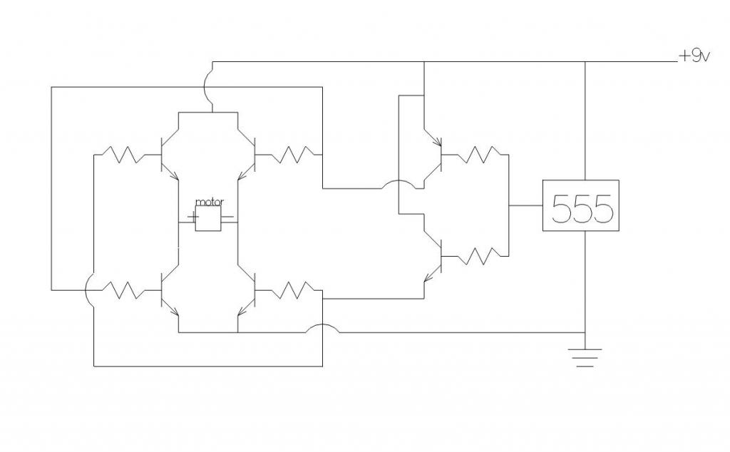
Help With DC Motor Control
So Im working on a project that will alternate either sourcing or sinking power to a DC motor. I have a working H-Bridge design that will flip the motor direction when either set of transistors is set High. I plan on running the switching with a general 555 timer circuit. The problem comes in when I have to connect the two together. I have a series of transistor hooked up to the H-bridge that turns on one of the sides when the PNP transistor is grounded or the other side when the NPN transistor is set high. However, if i connect the bases of the PNP and NPN transistors the motor runs. This is a problem because then the 555 timer cannot control the bridge. Heres my schematic

I think that all I need are some diodes or something, but I dont know what. Does anybody have any suggestions, or a better way to do this?
Thanks

I think that all I need are some diodes or something, but I dont know what. Does anybody have any suggestions, or a better way to do this?
Thanks


Comments
The top-switches in that bridge are emitter-followers, they will get hot - normally PNP transistors are used hi-side specifically to
get efficient saturated top-side switches - like this:
[ or were you wanting to PWM the bridge? - that's more complex ]
No Im not wanting to PWM the bridge, just flip the direction of the motor. But I dont completely understand your schematic. What are the P$1 and what connects to the 555 timer and what connects to the motor?