

OSEPP Gyroscope on Propeller I2C Bus
 waymond91
Posts: 15
waymond91
Posts: 15
Hey All!!
I am working at connecting some OSEPP brand sensors to propeller i2c bus. I have had success with the compass using one of the objects on obex (which confuses me because the i2c addresses don't correspond). I am fairly new to I2C, but I am always looking to understand the next layer.
The gyroscope uses the MPU3050 chip. Here is the register map for the chipset:
http://invensense.com/mems/gyro/documents/RM-MPU-3000A.pdf
Osepp also released an arduino code for the <wire> library. I know this works, I had it working on the arduino and later on the beaglebone. I would have put it in code tags, but I can't get the spacing write with a copy paste. Here is the link
http://osepp.com/learning-centre/start-here/gyroscope-sensor-module/
So I think I have something workable here. I have tried a bunch of different I2C objects without any success ( I also do enjoy poking around and trying to code as much as I can myself where possible). With a little help of existing libraries and a couple tutorials, I wrote this:
Here you can see what values I get when I print the received bytes from the data registers, and the calculated x-value:::
These are not usable values. They have no relevance to the motion of the sensor.
Any idea what I am doing wrong here all?? If I can get this working for gyroscope, I should be able to get it working for the accelerometer and compass as well. I will post what I work out here.
Also, has anyone been able to find some good I2C tutorials?? I have been dredging my way through, and bits and pieces are coming together. If I can get a better grasp I think it would be worth while to post a tutorial on instructables...
Anyway, let me know what you think!!
Thanks all!!
I am working at connecting some OSEPP brand sensors to propeller i2c bus. I have had success with the compass using one of the objects on obex (which confuses me because the i2c addresses don't correspond). I am fairly new to I2C, but I am always looking to understand the next layer.
The gyroscope uses the MPU3050 chip. Here is the register map for the chipset:
http://invensense.com/mems/gyro/documents/RM-MPU-3000A.pdf
Osepp also released an arduino code for the <wire> library. I know this works, I had it working on the arduino and later on the beaglebone. I would have put it in code tags, but I can't get the spacing write with a copy paste. Here is the link
http://osepp.com/learning-centre/start-here/gyroscope-sensor-module/
So I think I have something workable here. I have tried a bunch of different I2C objects without any success ( I also do enjoy poking around and trying to code as much as I can myself where possible). With a little help of existing libraries and a couple tutorials, I wrote this:
OBJ


    pst       :   "Parallax Serial Terminal"


CON


  _clkmode      = xtal1 + pll16x
  _clkfreq      = 80_000_000


  SDA  = 29         ' SDA of gyro to pin P1
  SCL = 28         ' SCL of gyro to pin P0

  GYRO_ON  = $68
  GYRO_OFF = $69


VAR


  long stack[8],x

PUB Main | count


  waitcnt(clkfreq/100_000 + cnt)     ' Power up delay
  pst.start(115200)
 repeat
   if (stack [0] ==0 & stack [1] == 0)
    x := stack[0] | stack [1]
    x := x-1
    x := ~x
    x := x
    pst.dec(x)
    'waitcnt(clkfreq + cnt)
    pst.newline
  repeat count from $1D to $1E
      SetPointer(GYRO_OFF,count)
      write(GYRO_OFF)
      stack[count- $1D] := read(false)                       ' Gather raw data from compass
      'pst.dec(stack[count - $1D])
      'pst.str(string("    "))


PUB SetPointer(Device,Register)


  start
  write(Device)
  write(Register)
  stop


pub write(value)


  value := ((!value) >< 8)


  repeat 8
    dira[SDA]  := value
    dira[SCL] := false
    dira[SCL] := true
    value >>= 1


  dira[SDA]  := false
  dira[SCL] := false
  result         := !(ina[SDA])
  dira[SCL] := true
  dira[SDA]  := true


pub read(aknowledge)


  dira[SDA] := false


  repeat 8
    result <<= 1
    dira[SCL] := false
    result         |= ina[SDA]
    dira[SCL] := true


  dira[SDA]  := aknowledge
  dira[SCL] := false
  dira[SCL] := true
  dira[SDA]  := true


pub start


  outa[SDA]  := false
  outa[SCL] := false
  dira[SDA]  := true
  dira[SCL] := true


pub stop


  dira[SCL] := false
  dira[SDA]  := false
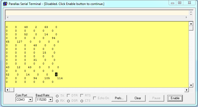
Here you can see what values I get when I print the received bytes from the data registers, and the calculated x-value:::
These are not usable values. They have no relevance to the motion of the sensor.
Any idea what I am doing wrong here all?? If I can get this working for gyroscope, I should be able to get it working for the accelerometer and compass as well. I will post what I work out here.
Also, has anyone been able to find some good I2C tutorials?? I have been dredging my way through, and bits and pieces are coming together. If I can get a better grasp I think it would be worth while to post a tutorial on instructables...
Anyway, let me know what you think!!
Thanks all!!

755 x 415 - 29K

755 x 410 - 25K
Comments
start
write device I2C address w/ write bit
write register address
start
write device I2C address w/ read bit
read byte (with NACK)
stop
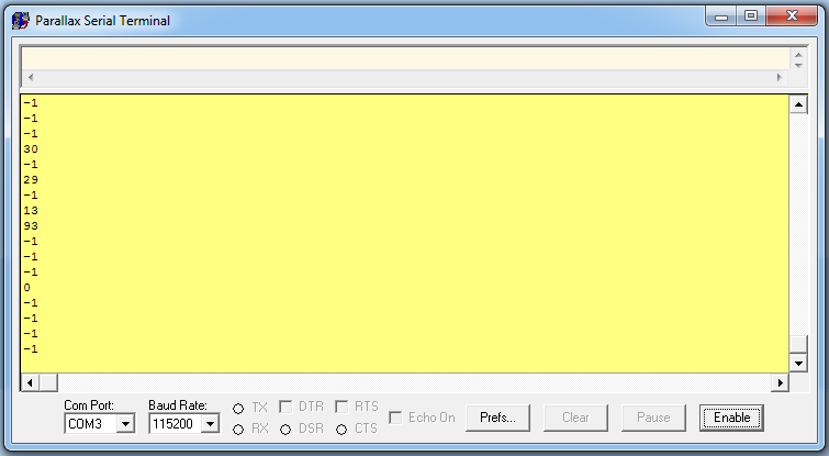
only now I get 255 for every received byte...
I am wondering if I am using the read/write bit correctly. I am using the same device address regardless of read/write operation. I tried adding "1" to the address before performing the final read, but that did not help, same result.
Also, I am confused about how the acknowledge bit works as well. The documentation for the chip says that NACK is defined by leaving SDA HIGH after the 9th cycle (ie, after the read is performed). Is it the duty of the microncontroller to acknowledge that the byte was read correctly? Am I doing this in my code?
Here is the latest:
OBJ


    pst       :   "Parallax Serial Terminal"


CON


  _clkmode      = xtal1 + pll16x
  _clkfreq      = 80_000_000


  SDA  = 29         ' SDA of gyro to pin P1
  SCL = 28         ' SCL of gyro to pin P0

  GYRO_ON  = $68
  GYRO_OFF = $69


VAR


  long stack[8],x

PUB Main | count


  waitcnt(clkfreq/100_000 + cnt)     ' Power up delay
  pst.start(115200)
 repeat
   if (stack [0] ==0 & stack [1] == 0)
    x := stack[0] | stack [1]
    x := x-1
    x := ~x
    x := x
    'pst.dec(x)
    'waitcnt(clkfreq + cnt)
    pst.newline
  repeat count from $1D to $22
      SetPointer(GYRO_OFF,count)
      write(GYRO_OFF -1)                         'I also tried subtracting 1 from the first write to this address. No satisfaction
      stack[count- $1D] := read(false)
      pst.dec(stack[count - $1D])
      pst.str(string("    "))


PUB SetPointer(Device,Register)


  start
  write(Device)
  write(Register)
  start


pub write(value)


  value := ((!value) >< 8)


  repeat 8
    dira[SDA]  := value
    dira[SCL] := false
    dira[SCL] := true
    value >>= 1


  dira[SDA]  := false
  dira[SCL] := false
  result         := !(ina[SDA])
  dira[SCL] := true
  dira[SDA]  := true


pub read(aknowledge)


  dira[SDA] := false


  repeat 8
    result <<= 1
    dira[SCL] := false
    result         |= ina[SDA]
    dira[SCL] := true


  dira[SDA]  := aknowledge
  dira[SCL] := false
  dira[SCL] := true
  dira[SDA]  := true


pub start


  outa[SDA]  := false
  outa[SCL] := false
  dira[SDA]  := true
  dira[SCL] := true


pub stop


  dira[SCL] := false
  dira[SDA]  := false
Any suggestions??
I am also looking at the Basic_I2C_Driver, I do not understand how the I2C frequency is set in this code. Is it default to 100Khz?
CON
   ACK      = 0                        ' I2C Acknowledge
   NAK      = 1                        ' I2C No Acknowledge
   Xmit     = 0                        ' I2C Direction Transmit


Var
  byte SCL, SDA


PUB Initialize(_SCL,_SDA)              ' An I2C device may be left in an


   SCL := _SCL
   SDA := _SDA                      '  invalid state and may need to be


   outa[SCL] := 1                       '   reinitialized.  Drive SCL high.
   dira[SCL] := 1
   dira[SDA] := 0                       ' Set SDA as input
   repeat 9
      outa[SCL] := 0                    ' Put out up to 9 clock pulses
      outa[SCL] := 1
      if ina[SDA]                      ' Repeat if SDA not driven high
         quit                          '  by the EEPROM


PUB Start


   outa[SCL]~~                         ' Initially drive SCL HIGH
   dira[SCL]~~
   outa[SDA]~~                         ' Initially drive SDA HIGH
   dira[SDA]~~
   outa[SDA]~                          ' Now drive SDA LOW
   outa[SCL]~                          ' Leave SCL LOW

PUB Stop


   outa[SCL]~~                         ' Drive SCL HIGH
   outa[SDA]~~                         '  then SDA HIGH
   dira[SCL]~                          ' Now let them float
   dira[SDA]~                          ' If pullups present, they'll stay HIGH


PUB Write(data) : ackbit
'' Write i2c data.  Data byte is output MSB first, SDA data line is valid
'' only while the SCL line is HIGH.  Data is always 8 bits (+ ACK/NAK).
'' SDA is assumed LOW and SCL and SDA are both left in the LOW state.
   ackbit := 0
   data <<= 24
   repeat 8                            ' Output data to SDA
      outa[SDA] := (data <-= 1) & 1
      outa[SCL]~~                      ' Toggle SCL from LOW to HIGH to LOW
      outa[SCL]~
   dira[SDA]~                          ' Set SDA to input for ACK/NAK
   outa[SCL]~~
   ackbit := ina[SDA]                  ' Sample SDA when SCL is HIGH
   outa[SCL]~
   outa[SDA]~                          ' Leave SDA driven LOW
   dira[SDA]~~


PUB Read(ackbit): data
'' Read in i2c data, Data byte is output MSB first, SDA data line is
'' valid only while the SCL line is HIGH.  SCL and SDA left in LOW state.
   data := 0
   dira[SDA]~                          ' Make SDA an input
   repeat 8                            ' Receive data from SDA
      outa[SCL]~~                      ' Sample SDA when SCL is HIGH
      data := (data << 1) | ina[SDA]
      outa[SCL]~
   outa[SDA] := ackbit                 ' Output ACK/NAK to SDA
   dira[SDA]~~
   outa[SCL]~~                         ' Toggle SCL from LOW to HIGH to LOW
   outa[SCL]~
   outa[SDA]~                          ' Leave SDA driven LOW


PUB WriteWait(devSel, addrReg) : ackbit
'' Wait for a previous write to complete.  Device select code is devSel.  Device
'' starting address is addrReg.  The device will not respond if it is busy.
'' The device select code is modified using the upper 3 bits of the 18 bit addrReg.
'' This returns zero if no error occurred or one if the device didn't respond.
   devSel |= addrReg >> 15 & 10
   Start
   ackbit := Write( devSel | Xmit)
   Stop
   return ackbit
Let me know what you think!
You are also missing the stop condition.
The ACK bit comes from however read the last byte. If you're sending data to a slave, then the ACK comes from the slave. If it's sending data to the Propeller (master), then the ack bit comes from the master.
In the second code post that you have, the speed is implied by the execution time of the code. There is no explicit clock speed setting. This works, since I2C is a synchronous protocol, so the precise clock speed doesn't matter as long as it's below a maximum.
I'd recommend that you use an already created driver to interface to the sensors.