

OSEPP Compass on Propeller I2C
 waymond91
Posts: 15
waymond91
Posts: 15
Hello All!
I have an OSEPP brand compass module (based of HMC5883L chip) that I need to connect to the propeller quick start via the I2C bus. Osepp has a demo code for the arduino <wire.h> library here :
http://osepp.com/learning-centre/start-here/compass-sensor-module/
Looks like this code simply writes bytes to specific registers within the sensor to set it in different modes and to read the compass values. I am using the Basic_I2C_Driver from the the i2cobject version 2 to communicate with the compass:
http://obex.parallax.com/objects/251/
Now when I look at the propeller quickstart board pinout, it seems like SCL is on 29, and SDA is on 28 (which does not agree with the i2c object). But when I used the i2c bus to communicate with altimeter module it seemed to work with SDA on 29 and SLC on 28. So I suppose this is correct.
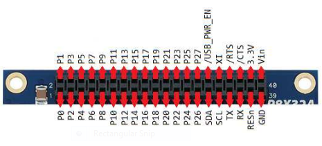
When I ran the demo app (included with the object above ^^^) with the default pins (SDA on 29, SCL on 28) it reported that it detected two I2C objects(I don't know why two, maybe the eeprom on the baord?? it did run through an eeprom demo). So it seems as though it found my compass somehow.
However, when I run this simple test, the propeller always reports the compass as missing:
I know this address is correct because I have had this module working on the arduino and beaglebone before. I have tried this configuration with and without 4.7k pullup resistors on the SCL and SDA lines. Maybe I need to configure the chip into continous write mode before I can sense it on the i2c bus??? I am not sure.
It seems to write a byte on the i2c bus using this object I simply need to pass it the (scl line, device address, the register address)?
Just to make referencing a little easier I will include the basic_i2c_driver object :
Any clues as to what I am doing wrong???
Thanks
I have an OSEPP brand compass module (based of HMC5883L chip) that I need to connect to the propeller quick start via the I2C bus. Osepp has a demo code for the arduino <wire.h> library here :
http://osepp.com/learning-centre/start-here/compass-sensor-module/
Looks like this code simply writes bytes to specific registers within the sensor to set it in different modes and to read the compass values. I am using the Basic_I2C_Driver from the the i2cobject version 2 to communicate with the compass:
http://obex.parallax.com/objects/251/
Now when I look at the propeller quickstart board pinout, it seems like SCL is on 29, and SDA is on 28 (which does not agree with the i2c object). But when I used the i2c bus to communicate with altimeter module it seemed to work with SDA on 29 and SLC on 28. So I suppose this is correct.
When I ran the demo app (included with the object above ^^^) with the default pins (SDA on 29, SCL on 28) it reported that it detected two I2C objects(I don't know why two, maybe the eeprom on the baord?? it did run through an eeprom demo). So it seems as though it found my compass somehow.
However, when I run this simple test, the propeller always reports the compass as missing:
CON
  _clkmode      = xtal1 + pll16x
  _xinfreq      = 5_000_000

  i2cSCL        = 28
'  i2cSDA        = 29


  COMPASS  = $1E


' debug - USE onboard pins
  pcDebugRX       = 31
  pcDebugTX       = 30


  ' serial baud rates
  pcDebugBaud     = 115200

VAR
  long  i2cAddress, i2cSlaveCounter


OBJ
  i2cObject      : "basic_i2c_driver"
  debug          : "Debug_PC"


pub Start
    ' start the PC debug object
    debug.startx(pcDebugRX,pcDebugTX,pcDebugBaud)

    ' setup i2cobject
    i2cObject.Initialize(i2cSCL)


    ' pause 5 seconds
    repeat 10
        debug.putc(".")
        waitcnt((clkfreq/2)+cnt)
    debug.putc(13)

    ' i2c state
    debug.strln(string("I2C Demo (v2)!"))


    if i2cObject.devicePresent(i2cSCL,COMPASS) == true
       debug.strln(string("COMPASS Present"))
    else
       debug.strln(string("COMPASS Missing"))
       waitcnt(clkfreq*3+cnt)
I know this address is correct because I have had this module working on the arduino and beaglebone before. I have tried this configuration with and without 4.7k pullup resistors on the SCL and SDA lines. Maybe I need to configure the chip into continous write mode before I can sense it on the i2c bus??? I am not sure.
It seems to write a byte on the i2c bus using this object I simply need to pass it the (scl line, device address, the register address)?
Just to make referencing a little easier I will include the basic_i2c_driver object :
CON
   ACK      = 0                        ' I2C Acknowledge
   NAK      = 1                        ' I2C No Acknowledge
   Xmit     = 0                        ' I2C Direction Transmit
   Recv     = 1                        ' I2C Direction Receive
   BootPin  = 28                       ' I2C Boot EEPROM SCL Pin
   EEPROM   = $A0                      ' I2C EEPROM Device Address


PUB Initialize(SCL) | SDA              ' An I2C device may be left in an
   SDA := SCL + 1                      '  invalid state and may need to be
   outa[SCL] := 1                       '   reinitialized.  Drive SCL high.
   dira[SCL] := 1
   dira[SDA] := 0                       ' Set SDA as input
   repeat 9
      outa[SCL] := 0                    ' Put out up to 9 clock pulses
      outa[SCL] := 1
      if ina[SDA]                      ' Repeat if SDA not driven high
         quit                          '  by the EEPROM


PUB Start(SCL) | SDA                   ' SDA goes HIGH to LOW with SCL HIGH
   SDA := SCL + 1
   outa[SCL]~~                         ' Initially drive SCL HIGH
   dira[SCL]~~
   outa[SDA]~~                         ' Initially drive SDA HIGH
   dira[SDA]~~
   outa[SDA]~                          ' Now drive SDA LOW
   outa[SCL]~                          ' Leave SCL LOW

PUB Stop(SCL) | SDA                    ' SDA goes LOW to HIGH with SCL High
   SDA := SCL + 1
   outa[SCL]~~                         ' Drive SCL HIGH
   outa[SDA]~~                         '  then SDA HIGH
   dira[SCL]~                          ' Now let them float
   dira[SDA]~                          ' If pullups present, they'll stay HIGH


PUB Write(SCL, data) : ackbit | SDA
'' Write i2c data.  Data byte is output MSB first, SDA data line is valid
'' only while the SCL line is HIGH.  Data is always 8 bits (+ ACK/NAK).
'' SDA is assumed LOW and SCL and SDA are both left in the LOW state.
   SDA := SCL + 1
   ackbit := 0
   data <<= 24
   repeat 8                            ' Output data to SDA
      outa[SDA] := (data <-= 1) & 1
      outa[SCL]~~                      ' Toggle SCL from LOW to HIGH to LOW
      outa[SCL]~
   dira[SDA]~                          ' Set SDA to input for ACK/NAK
   outa[SCL]~~
   ackbit := ina[SDA]                  ' Sample SDA when SCL is HIGH
   outa[SCL]~
   outa[SDA]~                          ' Leave SDA driven LOW
   dira[SDA]~~


PUB Read(SCL, ackbit): data | SDA
'' Read in i2c data, Data byte is output MSB first, SDA data line is
'' valid only while the SCL line is HIGH.  SCL and SDA left in LOW state.
   SDA := SCL + 1
   data := 0
   dira[SDA]~                          ' Make SDA an input
   repeat 8                            ' Receive data from SDA
      outa[SCL]~~                      ' Sample SDA when SCL is HIGH
      data := (data << 1) | ina[SDA]
      outa[SCL]~
   outa[SDA] := ackbit                 ' Output ACK/NAK to SDA
   dira[SDA]~~
   outa[SCL]~~                         ' Toggle SCL from LOW to HIGH to LOW
   outa[SCL]~
   outa[SDA]~                          ' Leave SDA driven LOW


PUB ReadPage(SCL, devSel, addrReg, dataPtr, count) : ackbit
'' Read in a block of i2c data.  Device select code is devSel.  Device starting
'' address is addrReg.  Data address is at dataPtr.  Number of bytes is count.
'' The device select code is modified using the upper 3 bits of the 19 bit addrReg.
'' Return zero if no errors or the acknowledge bits if an error occurred.
   devSel |= addrReg >> 15 & 10
   Start(SCL)                          ' Select the device & send address
   ackbit := Write(SCL, devSel | Xmit)
   ackbit := (ackbit << 1) | Write(SCL, addrReg >> 8 & $FF)
   ackbit := (ackbit << 1) | Write(SCL, addrReg & $FF)
   Start(SCL)                          ' Reselect the device for reading
   ackbit := (ackbit << 1) | Write(SCL, devSel | Recv)
   repeat count - 1
      byte[dataPtr++] := Read(SCL, ACK)
   byte[dataPtr++] := Read(SCL, NAK)
   Stop(SCL)
   return ackbit


PUB ReadByte(SCL, devSel, addrReg) : data
'' Read in a single byte of i2c data.  Device select code is devSel.  Device
'' starting address is addrReg.  The device select code is modified using the
'' upper 3 bits of the 19 bit addrReg.  This returns true if an error occurred.
   if ReadPage(SCL, devSel, addrReg, @data, 1)
      return -1


PUB ReadWord(SCL, devSel, addrReg) : data
'' Read in a single word of i2c data.  Device select code is devSel.  Device
'' starting address is addrReg.  The device select code is modified using the
'' upper 3 bits of the 19 bit addrReg.  This returns true if an error occurred.
   if ReadPage(SCL, devSel, addrReg, @data, 2)
      return -1


PUB ReadLong(SCL, devSel, addrReg) : data
'' Read in a single long of i2c data.  Device select code is devSel.  Device
'' starting address is addrReg.  The device select code is modified using the
'' upper 3 bits of the 19 bit addrReg.  This returns true if an error occurred.
'' Note that you can't distinguish between a return value of -1 and true error.
   if ReadPage(SCL, devSel, addrReg, @data, 4)
      return -1


PUB WritePage(SCL, devSel, addrReg, dataPtr, count) : ackbit
'' Write out a block of i2c data.  Device select code is devSel.  Device starting
'' address is addrReg.  Data address is at dataPtr.  Number of bytes is count.
'' The device select code is modified using the upper 3 bits of the 19 bit addrReg.
'' Most devices have a page size of at least 32 bytes, some as large as 256 bytes.
'' Return zero if no errors or the acknowledge bits if an error occurred.  If
'' more than 31 bytes are transmitted, the sign bit is "sticky" and is the
'' logical "or" of the acknowledge bits of any bytes past the 31st.
   devSel |= addrReg >> 15 & 10
   Start(SCL)                          ' Select the device & send address
   ackbit := Write(SCL, devSel | Xmit)
   ackbit := (ackbit << 1) | Write(SCL, addrReg >> 8 & $FF)
   ackbit := (ackbit << 1) | Write(SCL, addrReg & $FF)
   repeat count                        ' Now send the data
      ackbit := ackbit << 1 | ackbit & $80000000 ' "Sticky" sign bit
      ackbit |= Write(SCL, byte[dataPtr++])
   Stop(SCL)
   return ackbit


PUB WriteByte(SCL, devSel, addrReg, data)
'' Write out a single byte of i2c data.  Device select code is devSel.  Device
'' starting address is addrReg.  The device select code is modified using the
'' upper 3 bits of the 19 bit addrReg.  This returns true if an error occurred.
   if WritePage(SCL, devSel, addrReg, @data, 1)
      return true
   ' james edit - wait for 5ms for page write to complete (80_000 * 5 = 400_000)
   waitcnt(400_000 + cnt)
   return false


PUB WriteWord(SCL, devSel, addrReg, data)
'' Write out a single word of i2c data.  Device select code is devSel.  Device
'' starting address is addrReg.  The device select code is modified using the
'' upper 3 bits of the 19 bit addrReg.  This returns true if an error occurred.
'' Note that the word value may not span an EEPROM page boundary.
   if WritePage(SCL, devSel, addrReg, @data, 2)
      return true
   ' james edit - wait for 5ms for page write to complete (80_000 * 5 = 400_000)
   waitcnt(400_000 + cnt)
   return false


PUB WriteLong(SCL, devSel, addrReg, data)
'' Write out a single long of i2c data.  Device select code is devSel.  Device
'' starting address is addrReg.  The device select code is modified using the
'' upper 3 bits of the 19 bit addrReg.  This returns true if an error occurred.
'' Note that the long word value may not span an EEPROM page boundary.
   if WritePage(SCL, devSel, addrReg, @data, 4)
      return true
   ' james edit - wait for 5ms for page write to complete (80_000 * 5 = 400_000)
   waitcnt(400_000 + cnt)
   return false


PUB WriteWait(SCL, devSel, addrReg) : ackbit
'' Wait for a previous write to complete.  Device select code is devSel.  Device
'' starting address is addrReg.  The device will not respond if it is busy.
'' The device select code is modified using the upper 3 bits of the 18 bit addrReg.
'' This returns zero if no error occurred or one if the device didn't respond.
   devSel |= addrReg >> 15 & 10
   Start(SCL)
   ackbit := Write(SCL, devSel | Xmit)
   Stop(SCL)
   return ackbit


' *************** JAMES'S Extra BITS *********************

PUB devicePresent(SCL,deviceAddress) : ackbit
  ' send the deviceAddress and listen for the ACK
   Start(SCL)
   ackbit := Write(SCL,deviceAddress | 0)
   Stop(SCL)
   if ackbit == ACK
     return true
   else
     return false


PUB writeLocation(SCL,device_address, register, value)
  start(SCL)
  write(SCL,device_address)
  write(SCL,register)
  write(SCL,value)
  stop (SCL)


PUB readLocation(SCL,device_address, register) : value
  start(SCL)
  write(SCL,device_address | 0)
  write(SCL,register)
  start(SCL)
  write(SCL,device_address | 1)
  value := read(SCL,NAK)
  stop(SCL)
  return value
Any clues as to what I am doing wrong???
Thanks

465 x 211 - 129K