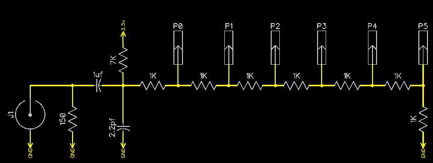
Video Flash ADC 6 grey levels.
 tonyp12
Posts: 1,951
I have not tested it,
but the idea is that the Prop pins hard switching at 1/2Vcc (1.65v) will act as fast comparators.
I terminated the incoming video at 150ohm instead of 75ohm, as to get a 1.5Vpp instead of 1Vpp
I put a 7k pull-up resistor to dc-bias the signal up by 1.5v.
2.2pf cap is to act as a 2.5mhz lowpass filter to filter out Chroma (if a color video).
The flash ADC will try to have all 6 pins at low if Hsync tip is active and each pin will asserted as voltage goes from 1.5 to 3.3v in six steps
Some values would need to be adjusted I'm sure, but could it work?


Comments
http://en.wikipedia.org/wiki/Resistor_ladder
http://en.wikipedia.org/wiki/Flash_ADC
Should be able to sample video in real-time and add HID or time etc.
Sorry, I mis-read your original post. I think you are correct, it should work for six levels.
Neat idea.
I would recommend using a DC restorer circuit ahead of the ADC, instead of just capacitively coupling it. The problem with capacitive coupling is that the "zero" level will vary with the overall brightness of the subject, leaving no absolute reference for the sync tips or the black level.
-Phil
As a practical implementation of a dc restore cicuit uses two capacitors, two op amps, and an S/H that adds a lot of parts and cost.
Maybe add 7th Prop pin for the ADC that will help tell the prop that the signal is to low or high.
and then dc-offset on a line by line bases as to act as the b and c examples below.
And attach a Prop pin in Duty mode (with added r/c) to the end of the ADC (lifting ground level) I could get variable offset on the fly.
Different types of video clamp
a) Diode or sync tip clamp, b) Keyed clamp with reference voltage used as a sync tip clamp
c) Keyed clamp used as a black level clamp, d) DC restore.
Neat ideas, hope they work.
Just wanted to point out the switching threshold is usually around 1.42v rather than Vdd/2, in case it affects your circuit calculations
cheers
tubular
Should I go with Sync clamp or Bias version?
http://rohmfs.rohm.com/en/products/databook/datasheet/ic/audio_video/video_amplifier/bh76330fvm-e.pdf
Being able to use 0.1 or 4.7uf input caps is a space saver.
Given the low level of quantized levels sync tip should be petty good.