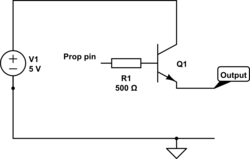
Drive TIP122 directly from a prop pin?
 Hugh
Posts: 362
Hi,
I've been trying to drive a TIP122 Darlington array directly from a prop pin. Does that make me insane, naive, overly optimistic or a combination of the three, or should this be possible.
With 5V at the collector and the prop pin providing 3.3V through a 500 ohm resistor to the base I expected more than 3.3V to be available at the emitter.

The output exactly matches the voltage at the base and it is the same with different transistors. A brief dalliance without the resistor didn't show any change. There's something fundamentally wrong in my approach but for the life of me I cant guess at what it is. I'd put a smaller transistor in first, but that would seem to defeat the point of using a darlington array.
Any ideas gratefully received. It is well over twenty years since I could even pretend to know about these things.
I've been trying to drive a TIP122 Darlington array directly from a prop pin. Does that make me insane, naive, overly optimistic or a combination of the three, or should this be possible.
With 5V at the collector and the prop pin providing 3.3V through a 500 ohm resistor to the base I expected more than 3.3V to be available at the emitter.

The output exactly matches the voltage at the base and it is the same with different transistors. A brief dalliance without the resistor didn't show any change. There's something fundamentally wrong in my approach but for the life of me I cant guess at what it is. I'd put a smaller transistor in first, but that would seem to defeat the point of using a darlington array.
Any ideas gratefully received. It is well over twenty years since I could even pretend to know about these things.


Comments
Why did you expect that ? - It is an emitter follower, which will always be < Vb.
How much less, depends on the load current.
With very low loads current, (eg a meter) the b-e resistors in a darlington give a direct path, and so you see "The output exactly matches the voltage at the base" - as the current load increases, that will drop to 2 x Vbe below Vb,
If you want Positive logic and voltage gain, a single Dual-NPN darlington will not work.
You need a NPN + PNP Darlington. As an example (this one for linear gain)
http://forums.parallax.com/attachment.php?attachmentid=96775&stc=1&thumb=1&d=1352345339
With NPN transistors it's far more common to run open collector, so you are switching ground. If you want to switch the high side, you should be using a TIP42C or the like, which is PNP and not NPN.
[Goes off and kicks himself]
Internally they obviously use mosfets or other transistors, but externally they are 4 or more pin black boxes that act much closer to an ideal component with a low voltage level enable input and higher power, low on resistance switching output (with options like short circuit protection should you need it).
I hate to see people struggling with Bipolar Junction Transistors in this day and age, except as an educational exercise.