

Building and customizing Parallax Stingray, an ongoing project log.
 rwgast_logicdesign
Posts: 1,464
rwgast_logicdesign
Posts: 1,464
I recently purchased a Parallax Stingray robot chassis. For those of you who may not have seen one for some reason, the product page can be found here:
Parallax Stingray, Product Page
The Stingray is very quality product, it is very durable and it makes a great platform for some one who wants to build a robot, but either doesn't have the proper tools, mechanical know how, or motivation to create there own chassis.
I decided to create this project log for a few reasons, #1 To help me keep on track and have a list of short term goals and problems to refer too, #2 To gain feed back from other Stingray owners, or maybe even inspire them in some way, and #3 Just to have a place to show my work.
This will be my first real robot, Ive gotten a few other self built or prebuilt chassis rolling around, but they all had issues mostly mechanical, that made them not worth pursuing to much farther. This is the reason I wanted a stingray, I wanted to get in to robotics with out having to deal with my wheels wobbiling or my surplus motors shorting etc
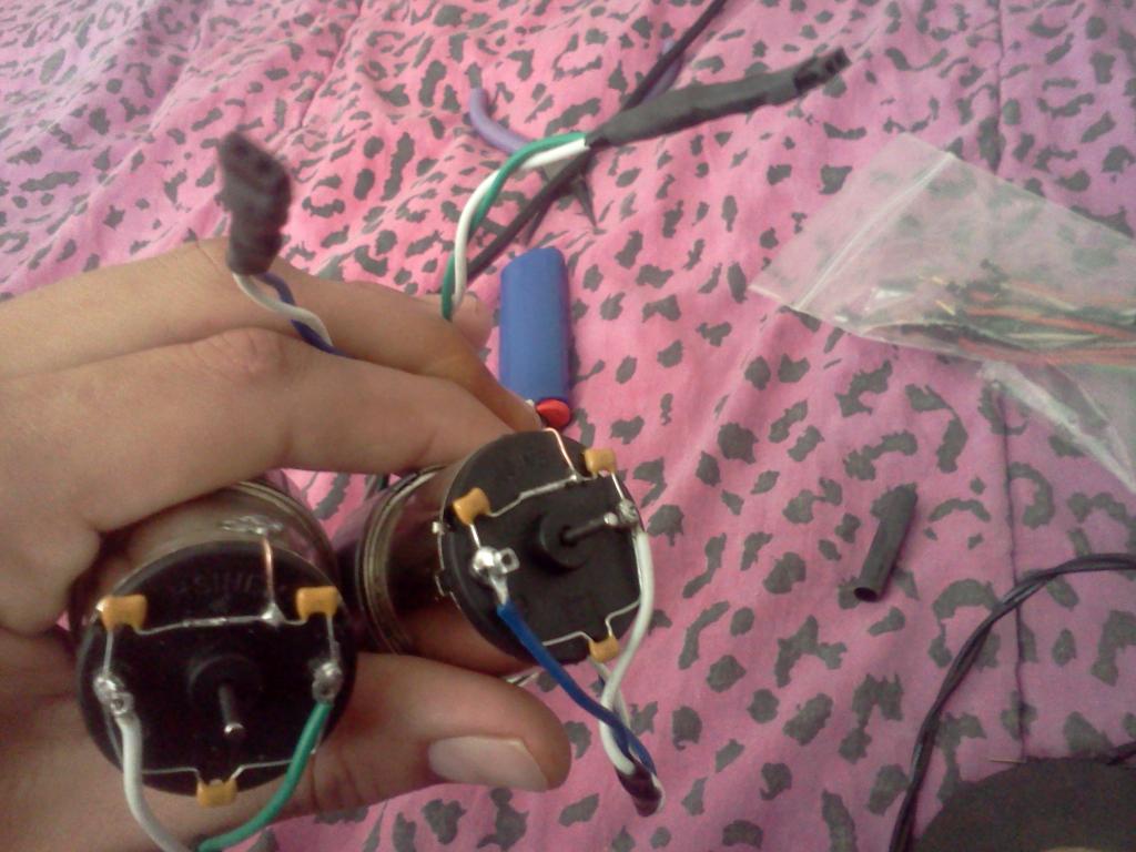
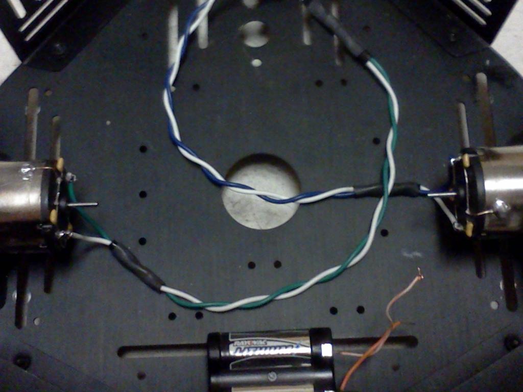
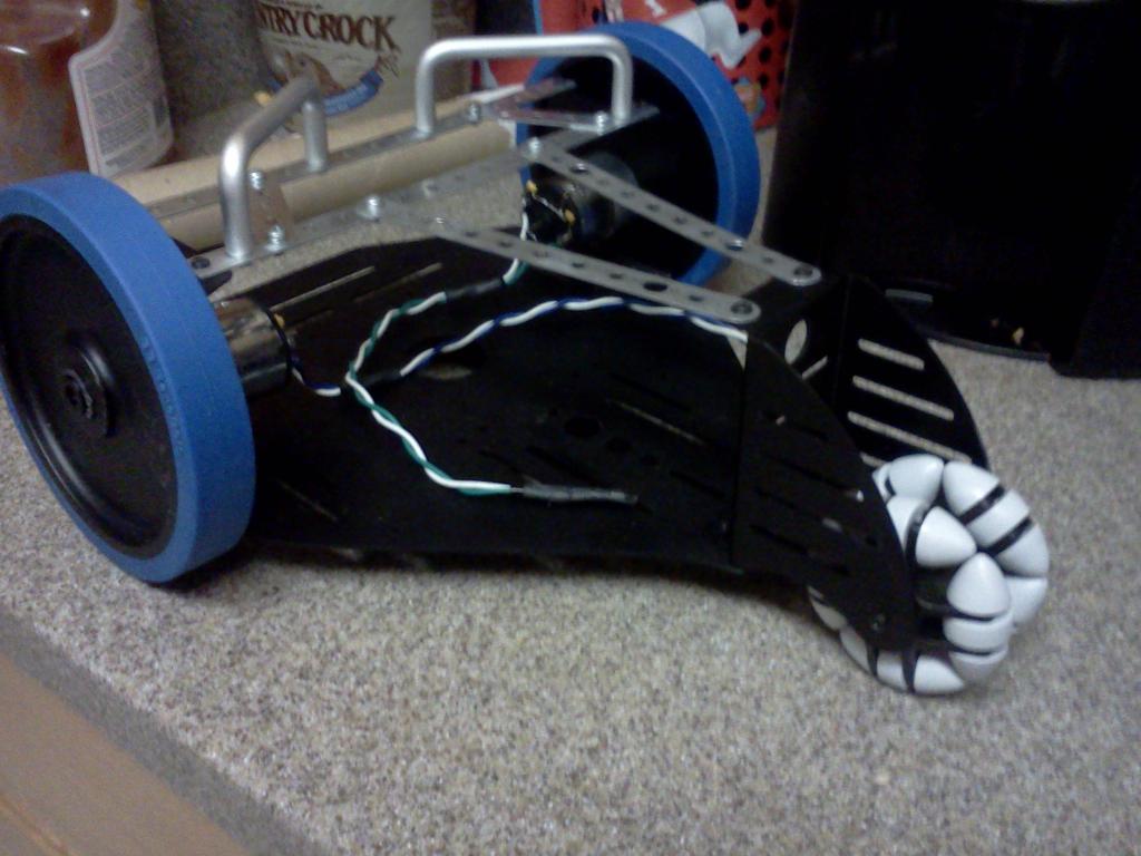
So far I have constructed my Stingray chassis, with a few customization's that I feel make it a little nicer. First of all I clocked my motors, originally the wire terminals on the back of the motors did not like up with each other, if one plans on implementing encoders on the back shafts this may make things a little more complicated. Here is a before and after picture to make things a bit more clear


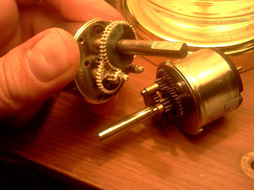
As you can see the motor terminals were off by about 90 degrees originally. All you need to do to "re-clock" the motors is remove the three screw in the gear head, once you can see the gear train, you will see two screws that hold base of the gearhead to the motor, in order to access them you may have to take the gear train apart, do this one motor at a time so you have a reference to reassemble it, the gear train itself isn't to complicated, but there are a few spacers that need to be re installed in the right place.
Once you can access the two screws that hold the gear head base in place, unscrew them, then twist the base to the appropriate position and screw it back in. You can find the right position fairly easily by setting the gearhead cover back on the base and twisting it around, while using the stingray chassis as a guide to make sure your screw holes line up right, and the motor terminals are facing the direction you want them too.
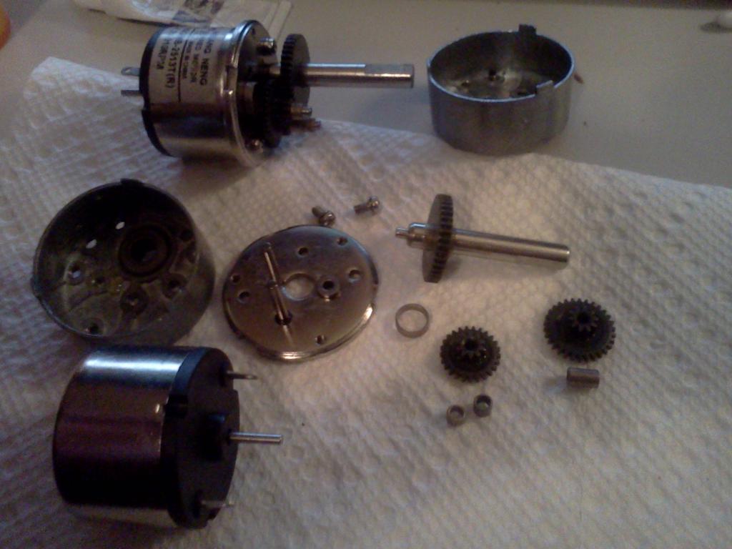
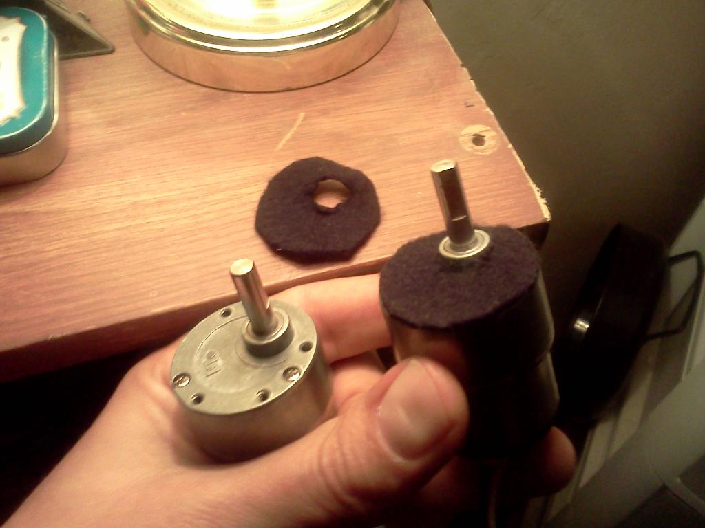
I made a very surprising find when I took these motors apart, they have metal gears! The Stingray manual shows white plastic gears, this is a very welcome upgrade! I also took it upon myself to clean the gear train with dish soap and water and then re-lube it using quality white lithium grease (available at any RC/hobby store). After the gear heads were clocked and the gears re greased I added noise filtering caps, and felt padding to keep the vibration noise down. I also decided to wire the motors so the colored wire was on the positive of the left motor and the negative of the right motor, this make it easy to determine which wire actually drives the motor forward. When I attached the capacitors and the motor wires to the terminals I made sure to keep them as close to the motor as possible this way there would be plenty of clearance on the back shaft.
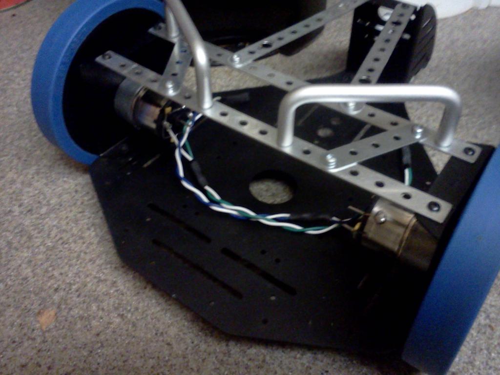
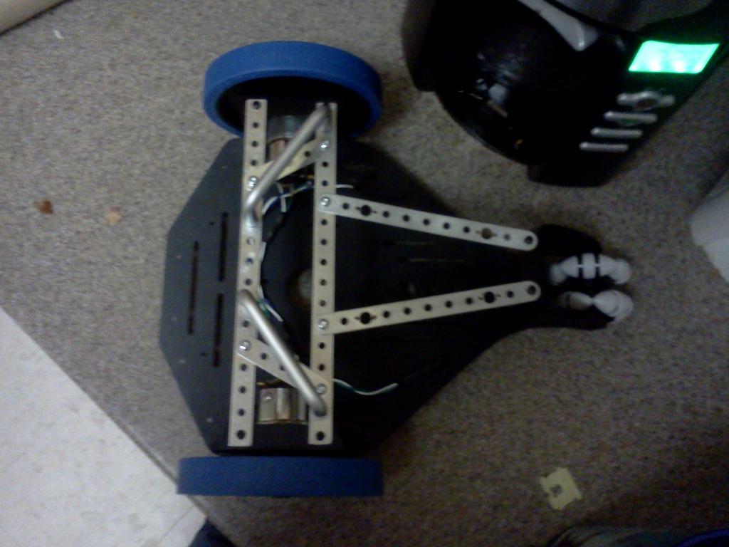
Next I started thinking about how I actually wanted to build my stingray, I ended up with a third deck piece, and I found that old erector sets I have have work out well as far as doing a little customization. Im still not sure exactly how the bot will look in the end, but I do know that I want to try and keep it clean, and keep a lot of the wiring on the very bottom deck where possible. In order to make it easier for me to start adding things to the chassis I wanted to keep the top deck off, but the sensor brackets can easily bend this way, especially if you pick the bot up by one of them. So I decided to unscrew all the brackets, except the ones that hold the motors in. Now that I had a fairly bear bottom deck to work with I wanted to make sure the motor brackets were supported well and the bot was easy to handle. This is where the Erector pieces first come in handy


While these are all minor modifications, they are just nice little details to make working with the stingray a lot easier, and make the bot a bit more quite. The felt pads worked really well until I actually screwed the motors in to the chassis. The significantly cut down noise but not as much as they did when I tested them by holding the motors against the bracket (running of course) with my hand. I have a feeling installing rubber washers around the mounting screws may be the issue here.
So far I have tested the chassis out by directly connecting the motors a 6v lithium camera battery. It works very well, it drives in a straight line all by itself, i.e no software correction. Even though these chassis are quicker than most robots it drives really smooth! I let it go in the parking lot of an apartment complex where it drove up a 30-35 degree hill and over killer speed bumps, with no issues at all, I was really surprised at how it handled on those speed bumps, I ran after it to catch it before it hit one but its so fast I didn't make it on time")
The next thing to do is get a battery pack in there, along with a propeller board and some switching regulators and get the chassis moving with simple open loop control, then record a figure 8. The bot will be using custom a custom made propeller board(s), but for testing purposes I will be using a BOE, or a different home made board I have lying around. The first things that will be implemented on this bot after the thing rolls, will be bumpers that use switches to stop to bot, wheel encoders, and ultrasonic sensors. I may end up needing sharp IR sensors too, my house has concrete walls so im not sure how well the ultrasonic is going to work without bouncing everywhere.
I just put in an order for a lot of the bits and pieces I need from parallax, i.e stand offs, crystals, caps, proto board things like that, along with some educational items, to keep things moving along. This stingray is a long term educational project, so im sure at some points it will stand still longer than others, I also have a host of non robotics projects I need to get done. I do have a lot of stuff to implement when im ready though, as far as sensors and modules go. Next update the chassis will be moving though
P.S
My Roomba chassis project (for those of you who saw the thread) has not been abandoned it has just kind of taken a back seat for a while until I can do what I want with it, which is make a cool trash can bot, the issue right now is mostly one of needing materials.
Parallax Stingray, Product Page
The Stingray is very quality product, it is very durable and it makes a great platform for some one who wants to build a robot, but either doesn't have the proper tools, mechanical know how, or motivation to create there own chassis.
I decided to create this project log for a few reasons, #1 To help me keep on track and have a list of short term goals and problems to refer too, #2 To gain feed back from other Stingray owners, or maybe even inspire them in some way, and #3 Just to have a place to show my work.
This will be my first real robot, Ive gotten a few other self built or prebuilt chassis rolling around, but they all had issues mostly mechanical, that made them not worth pursuing to much farther. This is the reason I wanted a stingray, I wanted to get in to robotics with out having to deal with my wheels wobbiling or my surplus motors shorting etc
So far I have constructed my Stingray chassis, with a few customization's that I feel make it a little nicer. First of all I clocked my motors, originally the wire terminals on the back of the motors did not like up with each other, if one plans on implementing encoders on the back shafts this may make things a little more complicated. Here is a before and after picture to make things a bit more clear
As you can see the motor terminals were off by about 90 degrees originally. All you need to do to "re-clock" the motors is remove the three screw in the gear head, once you can see the gear train, you will see two screws that hold base of the gearhead to the motor, in order to access them you may have to take the gear train apart, do this one motor at a time so you have a reference to reassemble it, the gear train itself isn't to complicated, but there are a few spacers that need to be re installed in the right place.
Once you can access the two screws that hold the gear head base in place, unscrew them, then twist the base to the appropriate position and screw it back in. You can find the right position fairly easily by setting the gearhead cover back on the base and twisting it around, while using the stingray chassis as a guide to make sure your screw holes line up right, and the motor terminals are facing the direction you want them too.
I made a very surprising find when I took these motors apart, they have metal gears! The Stingray manual shows white plastic gears, this is a very welcome upgrade! I also took it upon myself to clean the gear train with dish soap and water and then re-lube it using quality white lithium grease (available at any RC/hobby store). After the gear heads were clocked and the gears re greased I added noise filtering caps, and felt padding to keep the vibration noise down. I also decided to wire the motors so the colored wire was on the positive of the left motor and the negative of the right motor, this make it easy to determine which wire actually drives the motor forward. When I attached the capacitors and the motor wires to the terminals I made sure to keep them as close to the motor as possible this way there would be plenty of clearance on the back shaft.
Next I started thinking about how I actually wanted to build my stingray, I ended up with a third deck piece, and I found that old erector sets I have have work out well as far as doing a little customization. Im still not sure exactly how the bot will look in the end, but I do know that I want to try and keep it clean, and keep a lot of the wiring on the very bottom deck where possible. In order to make it easier for me to start adding things to the chassis I wanted to keep the top deck off, but the sensor brackets can easily bend this way, especially if you pick the bot up by one of them. So I decided to unscrew all the brackets, except the ones that hold the motors in. Now that I had a fairly bear bottom deck to work with I wanted to make sure the motor brackets were supported well and the bot was easy to handle. This is where the Erector pieces first come in handy
While these are all minor modifications, they are just nice little details to make working with the stingray a lot easier, and make the bot a bit more quite. The felt pads worked really well until I actually screwed the motors in to the chassis. The significantly cut down noise but not as much as they did when I tested them by holding the motors against the bracket (running of course) with my hand. I have a feeling installing rubber washers around the mounting screws may be the issue here.
So far I have tested the chassis out by directly connecting the motors a 6v lithium camera battery. It works very well, it drives in a straight line all by itself, i.e no software correction. Even though these chassis are quicker than most robots it drives really smooth! I let it go in the parking lot of an apartment complex where it drove up a 30-35 degree hill and over killer speed bumps, with no issues at all, I was really surprised at how it handled on those speed bumps, I ran after it to catch it before it hit one but its so fast I didn't make it on time
The next thing to do is get a battery pack in there, along with a propeller board and some switching regulators and get the chassis moving with simple open loop control, then record a figure 8. The bot will be using custom a custom made propeller board(s), but for testing purposes I will be using a BOE, or a different home made board I have lying around. The first things that will be implemented on this bot after the thing rolls, will be bumpers that use switches to stop to bot, wheel encoders, and ultrasonic sensors. I may end up needing sharp IR sensors too, my house has concrete walls so im not sure how well the ultrasonic is going to work without bouncing everywhere.
I just put in an order for a lot of the bits and pieces I need from parallax, i.e stand offs, crystals, caps, proto board things like that, along with some educational items, to keep things moving along. This stingray is a long term educational project, so im sure at some points it will stand still longer than others, I also have a host of non robotics projects I need to get done. I do have a lot of stuff to implement when im ready though, as far as sensors and modules go. Next update the chassis will be moving though
P.S
My Roomba chassis project (for those of you who saw the thread) has not been abandoned it has just kind of taken a back seat for a while until I can do what I want with it, which is make a cool trash can bot, the issue right now is mostly one of needing materials.
1024 x 768 - 89K
1024 x 768 - 73K

1024 x 768 - 74K

1024 x 768 - 85K

1024 x 768 - 91K

1024 x 768 - 71K
1024 x 768 - 81K
1024 x 768 - 77K
1024 x 768 - 86K
Comments
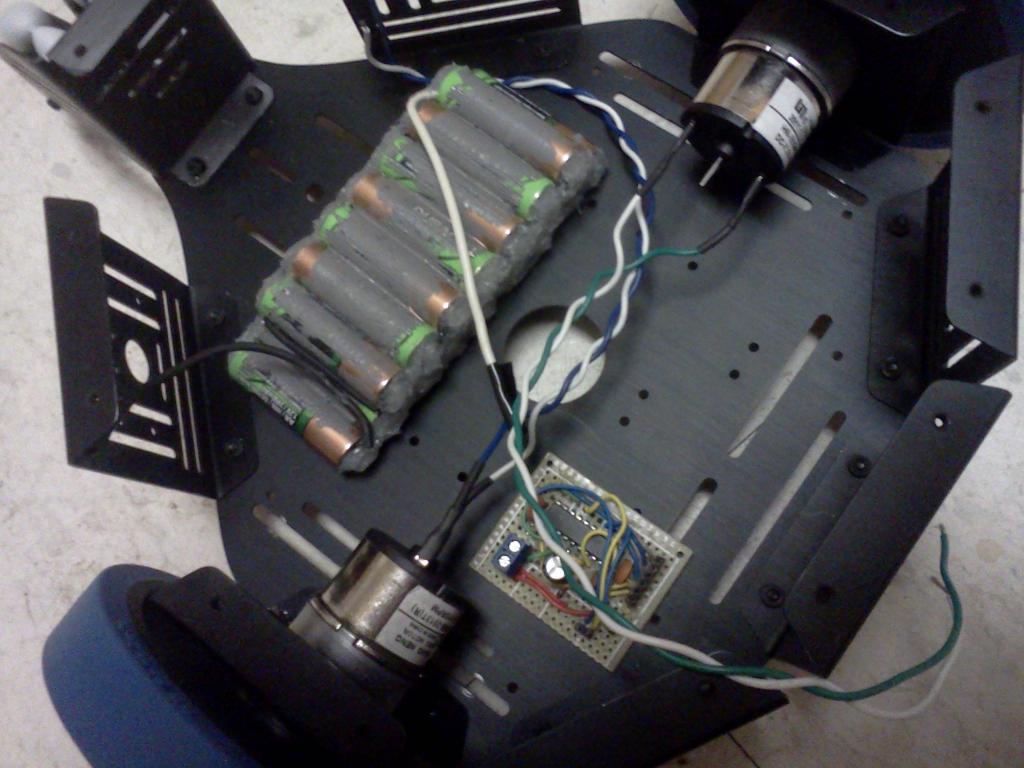
So I have 4 sting ray decks, and I plan on using at least 3 of them. Ive been working the last few days on getting the deck #1 and #2 out of erector set beta stage and actually building something usable. Once the innards of the sting ray are completed, along with the final brain I will post those too. As of now Im planning to use a quick start along with an Arduino chip and other IC's soldered to the proto board shown in these pictures. I will also be mounting a panning servo on the back a long with another UltraSonic sensor, this way I can make better decisions in reverse
The metal fastners on the front are to give me more expansion options in the future, as far as a bumper goes, or more sensors, I will be adding IR also. Right now they serve the purpose of connecting a make shift bumper that saves me from smacking the sonars in to objects, Ive already broken one this way.
EDIT:
Well it would seem as though I fried my quick start, a 12v wire touched it, I saw a small spark and now the prop tool can't find the propeller when I try to use it. Im not sure what Im going to do now...
I spent a lot of time with this board mostly becuase I was trying to learn a lot about mixed signal circuits and how to keep the digital noise out of the ADC's, I ended up doing a fairly decent job, for protoboard, at least I think. My LSB only floats about 3 out of 4090, so thats not so bad.
Here is a run down of the what is on the board
A: Programming port, a special board plugs into this and uses the prop plug to program the Prop and Arduino, along with reset buttons.
B: MCP3208 ADC 8 channels, 4 Analog Grounds.
C: I2C Stackable expansion bus
E: +3.3v/Ground
F: Main 64k EEPROM
G: Storage 64k EEPROM
H: MCP3208 ADC Chip
I: AVR Atmega328p Programmed with Arduino
K: Propeller chip
L: SPI Bus for MCP3208(and add on DAC) can be jumpered if not in use
M: 4 Pin Jumperable Bus to between AVR and Propeller, this configuration was chosen so I could use either standard RX TX serial, or a SPI like the X-Game station chameleon board
The board plugged in to the i2c expansion is a DS1307 module with temperature compensated oscillator for a bit better accuracy than a standard crystal.
It is basically a home made prop dev board connected to a 9v, and l6205 h-bridge powered by a 9.6v NiCad. The h-bridge circuit is a permanent solution, and the 9.6v NiCad is 2amp hours im not sure if it will ultimately become the main power source for this bot or not.
Thanks for posting the videos and thanks for taking time to document this project.
This looks great so far.
Do have anything to use as a remote? I think it would help if you could manually control it as you figure out how to get to behave autonomously.
A couple of those cheap Nordic modules could be used with a second microcontroller as a remote control. You could even use a TV remote if your going to be indoors.
This is great. I'm excited to see how this progresses.
(BTW, is your camera sad? Those videos sure looked blue.)
Glad to see you have a rolling bot. It just gets better from here!!!!
LOL, about the camera, its the ROM on my phone, im not sure why but it wont let me adjust my camera brightness/color although it does everything else better.
As far as remote control goes im really just not sure what I want to do yet, I haven't received my nordic modules yet but im not sure if they are really where I want to start for wireless, I didnt realize they were not transparent serial devices. I have this little thing called a zipitZ2 you can get for about 30 bucks, it has ttl serial, wifi, usb, etc Im thinking about putting it on my bot to had a screen for visualizing data and running a debug terminal, but I could also plug a BT key in to it as well or an AdHoc WiFi connection. I think for now the easiest answer would be transparent serial over BT with my phone. Already have an app written specifically for serial robot control, it even lets you send custom serial commands.
I was acually wondering if anyone knows a way I could buy or have final drive gears made for these motors. I think without current feedback this bot is going to be a big pain in the but trying tight maneuvers in a house. I know there are other motors out there that will fit in the sting ray, I would think two gears may be cheaper...
Just wondering.
I plan to implement my own PWM code at some point, Im no where near the skill level with the prop I want to be to do this though. I wrote my own duty cycle routines for a 32khz pwm controller for Arduino, originally intending to use it as the main motor controller in my project, ive come to my seanses since then though
I don't think adding gears is a good idea. If you want slower motors, you should ask erco where he got his "low gear ratio motors from China" he's planning on using with his Stingray.
Trying to add gears yourself will just put you back where you were trying to get surplus motors to work.
As I just told erco, I think fast motors can be tamed with encoders (see bottom of linked post). The Rover 5 robot is just about impossible to drive at very slow speeds without encoder feedback. I think the same technique would work with the Stingray.
Xanadu it is a very nice platform, the only issue if you want to use it inside is to figure out how to tame its speed, as Duane says. If you roll around at maybe 40% speed you have enough torque but you will be smashing stuff up while testing. The idea here is to run a 10% duty cycle and monitor the motors with encooders/current shunts, and apply more juice when the bot stalls on a sock your girlfriend left on the floor.
http://obex.parallax.com/objects/526/
But I have a few issues with it, first off it does not support Enable Pins, found on most H-Bridges. That is a very easy fix Ive already implemented. My bigger issues is #1 the fastest it can run is 8000Hertz, this is to slow and make the motors whine quite a bit, especially when running at very low duty cycles near 10-20%. Secondly and more importantly, the code states set the duty cycle to 0 to break, when I set the duty cycle to 0 the wheels barely slow down. Ive tried to implement fast breaking by setting both the forward and reverse pins Hi, but this isnt working, im guessing it must have something to do with the counters controlling the pin.
The rest of the objects on Obex, that ive looked at, I either dont follow how to set them up, or are just not very easy to get working with a regular 3 pin h-bridge, or finally have a bunch of code for encoders and PID built in, this would be fine later but not for right now.
Ive written my own motor control routines for Arduino running at a 32Khz PWM and they seems to work fairly well, but it is just much easier to get a good fast PWM routine set up on Arduino, Im guessing with the Prop to get a 32khz PWM cycle one would have to use PASM with the counters. So anyways I was just wondering what all objects anyone out there may be using to do speed control on a two wheel bot?
My first figure 8!
First let me give a StingRay specific tip. I read some threads where MicroControlled, and Bomber had said all the screws fell out the bottom of there stingray with prolonged Hi Speed use. Well UI was testing my stingray out on asphalt the other night at 100% duty, guess what I lost a screw! Only one and I have replacements on hand so no biggie. Anyways I added lock tight to all the motor screws and the motor mount plates when I put the bot togather. I will now add lock tight to every screw that goes in the bot, I suggest any other stingray owners go get a 5 dollar tube of blue lock tight at AutoZone and make generous use of it.
As far as this project is going the top three things on my list are to get bluetooth up and going along with the Rocket Labs Android robot remote protocol, Get Encoders on the wheels, and get some Sonar working. The Sonar and BT will probably come first as they will help me test and debug features without slamming in to walls. I tried mechanical feedback already, it was Ok but not a reliable means of stopping crashes completely, so I decided to come back to a bumper later with a much better design, using springs.
As for motor control Im still using Kyes driver I fixed any issues I had with it before. I do plan on implementing my own PWM, because I want to change carrier frequency on the fly. My testing shows me that about 100-200hz is a good carrier when going slow but the Khz range is much smoother in the mid speed to fast range. Basically this will come later It requires PASM and Im not there yet. Ive also been looking at a separate chip to handle my PWM but I really need to research that before I go down that road.
EDIT: Aww what the heck, here it is. The bot smacks a trash can at the end, I think I did a decent job for whipping this code up in 20 minutes or and so being it is the first robot Ive ever programmed.
I really cant wait to get encoders on this bad boy, I have so many ideas for them. I really need to get Blue Tooth up and running first so I can manually control the bot though. Ive just been having a hard time setting the BT module up, I really need to change the baud rate. The eb301 module I have is much more complicated than those cheap e-bay ones.
Also I ordered some reflective sensors for my encoders, and some nordic modules to use for hi speed data, I will eventually build a custom hardware remote to replace my phone as a controller and I intend to use the nordics for that. But i am still waiting on both of these items to show up.
In order for it to work with the BoeBot you need one of these:http://www.eit.lth.se/fileadmin/eit/courses/edi021/datablad/Logik/CMOS/mc14049ub.pdf
Not sure if that is the case with the Prop or not, but the youtube video may give you some pointers.
You can see how awful the soldering irons tip is! This just goes to show, anyone can use Surface Mount stuff!
Secondly I finished up the little adapter board to let me program either the Propeller or Arduino by simply moving a 4x2 jumper in to the right position. Here are some updated pictures of whats going on, I will most likely end up building a much better H-bridge using parallel ST L6205 chips in the future, I would like to multiplex the the motor control pins and add the current sense stuff on the same board.
I'm interested in your plan for the feedback loop. I'm a software-geek and the hardware side of things go over my head generally
Thanks for showing your bot and your ideas!
dgately
OK
How do you break a Weller?
(I'm sure the answer will be more painful than the question.)
@dgately, Im no expert either, this is why I chose to build a robot. For me a robot teaches everything from building a nice rechargeable switching power system to laser range finding. It just all depends on how much you and how much you make. I have committed to making everything from scratch that I possibly can using proto board and a soldering iron. I have just now started to learn about analog electronics including, ADCs, DACs, opamps, passive filters etc. As the title states, this is an ongoing project, it is going to take quite a long time, especially when I go back to work. Unfortunately I have another project I am doing as a present which is going to eat up all my time for a while.
Anyways to the motor control, this is basically how the hardware works. You connect a .005ohm (such a low value is chosen to practically eliminate voltage drop) resistor in series with your motor then you measure the voltage drop across that resistor, using ohms law you can easily tell how much current is passing through it. The problem is the voltage drop of such a small resistor is very very low, for example at the rated stall current of the sting rays motor 4.5 amps, the resistor will only generate 22mv of drop, now imagine the drop when the motor only draws 70mA, there is no practical way to read that voltage with most ADCs. Buy connecting an amplifier like the one above, you can multiply the resistors dropped voltage. In my case I will be using a hi side amp with a 200v gain. This mean when the motor stalls at 4.5A the resistor will drop 22mv, then the amp will multiply that by 200, giving 4.4vs to send to the ADC, you can see how this is much more convenient than 22mv!
As far as my plans for the software, this is what I am thinking. So a stingrays motors are geared very HI, they are gutless when sending then a 10% PWM signal, the bot will roll but get hung up on the edge of a rug, or a sock. Well we all know that more current equals more torque. Now when running at a low PWM and one wheel gets hung up on a sock this will cause your current to rise, and your encoder readings to slow down. The idea is to up the PWM to the hung up wheel, while sampling the current amplifier. By boosting the duty cycle you will up the voltage to that wheel, causing the current to start going back down again, until it is equal with the motor that is not struggling. This should in theory allow you to keep the torque constant no matter what the obstacle is, whether it be a sock or a 30% incline.
Im not sure that made any sense, let me know if it was at all helpful!
So, using encoders won't provide enough data to enable matching motor speeds when one wheel is required to overcome resistance (socks, inclines, etc...)? I've been using encoders to develop a speed-matching method because my bot's motors never seem to turn as the same speed for the same PWM values. They're as much as 8% off in straight-line tests when the wheels have matching surfaces to run on. So, it's possible that your method will help this case as well!
Thanks,
dgately
There are all kinds of other reasons to get current feedback besides PID though, I am interested in monitoring power consumption so my bot can make smarter decisions based on how much juice it has left. I can also make sure the motor never draws 4.5amps (It's max stall current) using current feedback, this was the original reason for wanting to sense current. Like I said I have not got all the details worked out yet, I am still a bit afraid taking voltage samples on the motor leads may not be all I need to do to calculate there current draw. Since the motors are receiving a PWM signal, will the ADC return a hi voltage then a low voltage of the signal, or will I get the average voltage like you see on a meter, If so I may need to stick a comparator in there, or use some kind of voltage to RMS chip like a meter would use to read AC.
IDK what Im doing, I just think I do sometime