[SOLVED] inverting the output pin connected to CTRA??
Hi,
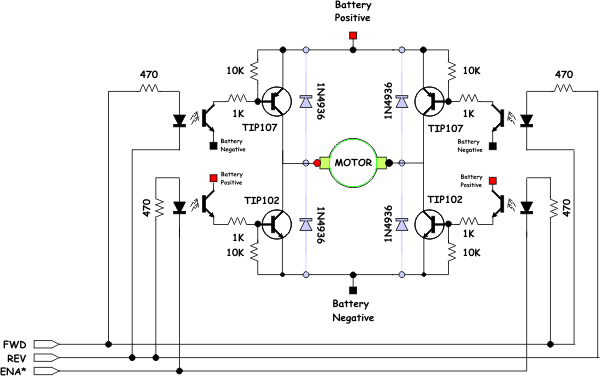
I have a servo H-Bridge that i built acording to the schematic below. it seems to be a little backwards compared to most of the others ive seen where the Enable pin is an active low instead of High.

H-Bridge Truth Table:
_______________________________________________________
FWD REV ENA*
1 0 0 - Turn on upper left source and lower right sink. (go forward)
1 0 1 - Disable lower right sink. When fed a PWM signal the bridge modulates the "forward" current through the motor.
1 1 0 - Turn on both lower left sink and lower right sink, shorting the motor "Braking."
1 1 1 - Disable both lower sinks. When fed a PWM signal the bridge modulates the "braking" of the motor.
0 1 0 - Turn on the upper right source and lower left sink. (go backward)
0 1 1 - Disable lower left sink. When fed a PWM signal the bridge modulates the "reverse" current through the motor.
0 0 0 - Turn off all sources and sinks. "Coast" motor is not engaged at all.
0 0 1 - Turn off all sources and sinks in a different way, same effect though.
_______________________________________________________
ok, so when i use a method like this:
by setting DUTY to 100
the output would be constantly high (or 1) and the motors are Not Enabled
and by setting DUTY to 0
the output would be constantly low (or 0) and the motors are Enabled
so my H-bridge needs the complete opposite!
i was successful at writing a program where 100 = "stopped" and 0 = "full power"
but things were getting messy in a hurry.
the only way i can think of doing this is to use something like a 74LS04 Not Gate connected to the output pins, but i keep telling myself there's an easier way to accomplish this!
if anyone has any suggestions on how to invert the pin's output controlled by cntra's output i would greatly appreciate it!!
Thanks
I have a servo H-Bridge that i built acording to the schematic below. it seems to be a little backwards compared to most of the others ive seen where the Enable pin is an active low instead of High.
H-Bridge Truth Table:
_______________________________________________________
FWD REV ENA*
1 0 0 - Turn on upper left source and lower right sink. (go forward)
1 0 1 - Disable lower right sink. When fed a PWM signal the bridge modulates the "forward" current through the motor.
1 1 0 - Turn on both lower left sink and lower right sink, shorting the motor "Braking."
1 1 1 - Disable both lower sinks. When fed a PWM signal the bridge modulates the "braking" of the motor.
0 1 0 - Turn on the upper right source and lower left sink. (go backward)
0 1 1 - Disable lower left sink. When fed a PWM signal the bridge modulates the "reverse" current through the motor.
0 0 0 - Turn off all sources and sinks. "Coast" motor is not engaged at all.
0 0 1 - Turn off all sources and sinks in a different way, same effect though.
_______________________________________________________
ok, so when i use a method like this:
PUB PWM(pin) | x, n , deadline , onepercentticks

dira[pin]~~
deadline := cnt
onepercentticks := clkfreq/30_000
repeat
  waitcnt(deadline += onepercentticks*100)
  ctra := 0
  frqa := 1
  phsa := -(onepercentticks * ( 1 #> DUTY <# 100))
  ctra := (%0_00100 <<26) + pin
by setting DUTY to 100
the output would be constantly high (or 1) and the motors are Not Enabled
and by setting DUTY to 0
the output would be constantly low (or 0) and the motors are Enabled
so my H-bridge needs the complete opposite!
i was successful at writing a program where 100 = "stopped" and 0 = "full power"
but things were getting messy in a hurry.
the only way i can think of doing this is to use something like a 74LS04 Not Gate connected to the output pins, but i keep telling myself there's an easier way to accomplish this!
if anyone has any suggestions on how to invert the pin's output controlled by cntra's output i would greatly appreciate it!!
Thanks


Comments
Don't the counter have a NOT mode where one is the inverse of the the other? I thought I remember reading that in the manual.
..and you don't need to set the counter new in every loop, just once before the repeat loop:
Andy
as soon as i get home today i will investigate these suggestions and post the results.
p.s.
I apologize for these novice questions, i am a beginner at using the counters but definitely see their usefulness and really want to learn! so thanks for baring with me
No way that will work, as it's to fast with 12.5ns pulses.
No h-bridge switch that fast and when going through opto-isolators will smooth out the signal even more.
Using NCO will give slower square waves, but fixed at 50% duty.