Melexis 90217, or.. I got ticks, now what?
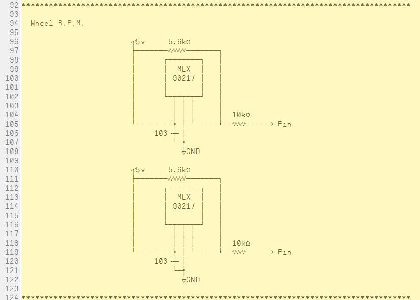
I am using this Melexis 90217 Hall_Effect sensor Circuit..

36 teeth on a 4 7/8" diameter Tyre at up to 350 rpm.
(36*350)/60 = 210 ticks per second? is that right?
And there are two tires, so thats like 420 ticks per second, right?
What am I going to do with all those ticks?
What do you do with your ticks?
-Tommy

36 teeth on a 4 7/8" diameter Tyre at up to 350 rpm.
(36*350)/60 = 210 ticks per second? is that right?
And there are two tires, so thats like 420 ticks per second, right?
What am I going to do with all those ticks?
What do you do with your ticks?
-Tommy


Comments
There's help for that:
-Phil
210 ticks per second? ... yes, that's correct. Another way to look at it is to take your RPM and convert it into RPS, then multiply that by the number of teeth.
350 rpm = 5.8333 rps ; X 36 = 210 Hz or ticks per second.
And there are two tires, so thats like 420 ticks per second, right? ... You don't add them typically, but rather look at them together. i.e. if your goal is to maintain a straight line you want to keep them as close as possible to one another. By determining the amount of error (or difference) between them you can adjust the steering mechanism slightly to correct for the error.
What am I going to do with all those ticks? ... As I mentioned you can use them to detect the error, but you can also just use them as a reference RPM and compare the error that way instead of comparing it to the other wheel. i.e. suppose your target speed is 300 rpm (180 ticks) if the returned number of ticks is greater than 180, then you know to reduce the PWM on than motor or adjust the steering... likewise if the returned number of ticks are less than 180, then you know to increase the PWM on that motor or adjust the steering. This way each motor is independent of one another but still mechanically locked through the floor ... there will still be unavoidable slippage.
So, what is a good way to count the ticks? (the hardware ticks, not the blood sucking ticks..)
CTRA and CTRB seem like the way to go.. just not sure how to go about it.
I mean, which Counter mode would be good for this type of counting, Seems like POS detector would work.
But there is NEG detector, and NEG detection with feed back, and, and... 30 other choices for counting...
A side question about the circuit in post #1, The 5.6k resistor is a pull-up, yes?
Can I substitute a 10K resistor for that, or is 5.6K a critical value?
I accidently ran the circuit with no pull-up at all, and it seemed to work just fine, That is why I ask.
Also, the data sheet shows an "Extreme Environment" circuit, Would I be better off using that circuit in a StingRay?
I panicked when I saw the two diodes pointing at each other...
-Tommy
Remember that a (quadrature) encoder uses two sensors per wheel. According to wikipedia, a single sensor is called a tach sensor.
I mostly agree with Beau (and PhiPi in the straight-line thread), in that it's about keeping track of the difference in wheel ticks between wheels. But instead of speed/rpm, I keep track of the overall tick count (distance). It's quite different.
BTW, I hope this doesn't mean you're giving up on your signature tailwheel steering. That would be a travesty! Add a steering tailwheel to your Stingray. Maybe Expo will be the place to showcase our hacked Stingrays.
Count on it!. Actually, I was hoping you(the servo master) could help find a certain size servo, A servo that is as
powerful as the the standard servo Parallax sells, but, at least 1/4" shorter in length...
-Tommy
You just answered your own question.
Standard Parallax Servo + Chop saw= custom fit!