Shop OBEX P1 Docs P2 Docs Learn Events
What to put on a Propeller Quickstart layout that has wide open spaces? — Parallax Forums

What to put on a Propeller Quickstart layout that has wide open spaces?

WBA ConsultingWBA Consulting Posts: 2,933
edited 2013-01-31 13:58 in Propeller 1
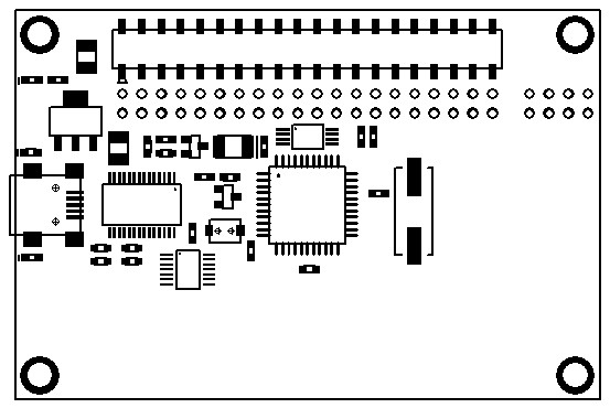
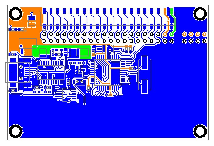
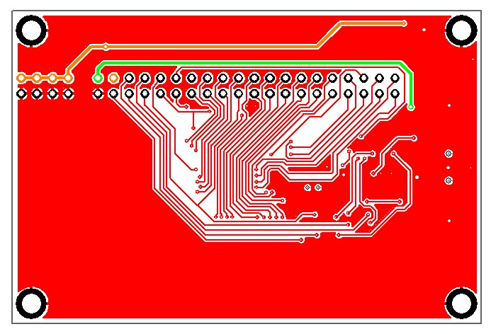
So, I am working on my DipTrace skills and grabbed the design files for the Quickstart to use as a base schematic/layout combo. Well, my skills are getting much better (even learned how to tweak copper pours) and after about 3 hours of "learning", I ended up with the attached layout. Basically I removed the LEDs, resistive touch pads, associated buffers and pullups, delta sigma circuit, crystal option, moved the reset circuit, and cleaned up lots of traces and ground planes affected by my changes. I still need to work on my schematic skills as it is missing the mounting holes, so if you renew the board from the schematic, they disappear, but I think the layout shows some serious potential of the Quickstart format.

What should go in all that space?

Quickstart_no-peripherals1.jpg


2nd Prop (3)
SRAM/Flash DIP8 socket (2)
LiPo connection/charging circuit (2)
5 volt supply (2)
ADC chip (1)
Micro SD socket
DC Jack
PS2 socket(s)
TV out
Flux Capacitor
VGA Circuit
???
553 x 370 - 41K
704 x 479 - 108K
693 x 472 - 88K
687 x 471 - 168K

Comments

  • MacTuxLinMacTuxLin Posts: 821
    edited 2013-01-09 22:49
    IMHO, I would add circuits for wireless & battery. So, at least the target projects for this would not overlap those that QS are already targeting....just my 2-cents worth....
  • TorTor Posts: 2,010
    edited 2013-01-10 01:39
    SRAM socket?

    -Tor
  • ErNaErNa Posts: 1,742
    edited 2013-01-10 01:41
    Place a second propeller. Only the chip and two pins to communicate with the first and xtal out of master to xtal in of slave. This would lower the barrier for multi processing a lot as there is hardware on the desktop. And make a connection for the raspberry pi.
  • cavelambcavelamb Posts: 720
    edited 2013-01-10 06:34
    5V regulator, SRAM and IR remote detector...
  • Oldbitcollector (Jeff)Oldbitcollector (Jeff) Posts: 8,091
    edited 2013-01-10 06:37
    ErNa wrote: »
    Place a second propeller. Only the chip and two pins to communicate with the first and xtal out of master to xtal in of slave. This would lower the barrier for multi processing a lot as there is hardware on the desktop. And make a connection for the raspberry pi.

    I'd like to "second" this...
  • DrNowDrNow Posts: 6
    edited 2013-01-10 08:17
    MacTuxLin wrote: »
    IMHO, I would add circuits for wireless & battery. So, at least the target projects for this would not overlap those that QS are already targeting....just my 2-cents worth....

    I second the motion for battery circuitry with the ability to charge a LiPo battery from a USB connection, and a connector for the battery.
  • photomankcphotomankc Posts: 943
    edited 2013-01-10 10:01
    I2C multi-channel ADC would be very nice. Lack of ADC is a constant burr in my side on propeller boards.
  • mindrobotsmindrobots Posts: 6,506
    edited 2013-01-10 13:24
    ErNa wrote: »
    Place a second propeller. Only the chip and two pins to communicate with the first and xtal out of master to xtal in of slave. This would lower the barrier for multi processing a lot as there is hardware on the desktop. And make a connection for the raspberry pi.

    Third for this! ......plus a connector of some sort to make the pins of the second prop available to connect to something.

    Socket for SRAM/Flash 8pin DIP?
  • WBA ConsultingWBA Consulting Posts: 2,933
    edited 2013-01-10 16:58
    Really!?! no votes for a flux capacitor? You guys are letting me down...... :lol:

    Anyhow, I updated the first post with number of votes for each item. I already started on my schematic updates and creating parts for a few items.
    ErNa wrote: »
    And make a connection for the raspberry pi.
    What would this consist of?
  • cavelambcavelamb Posts: 720
    edited 2013-01-10 17:28
    Transistor array?

    Mosfets or such?
  • Oldbitcollector (Jeff)Oldbitcollector (Jeff) Posts: 8,091
    edited 2013-01-10 17:32
    Next question Andrew, Can I stock this.. :)

    Two Propellers on a Quickstart footprint is a winner. Any chance of adding the ability to interconnect any other pin between the Propellers while you are at it?

    Jeff
  • dgatelydgately Posts: 1,621
    edited 2013-01-10 17:50
    Really!?! no votes for a flux capacitor? You guys are letting me down...... :lol:

    Anyhow, I updated the first post with number of votes for each item. I already started on my schematic updates and creating parts for a few items.

    What would this consist of?

    Remember that the Raspberry Pi's GPIO is 5V-based...

    A link to the Raspberry Pi Wiki for the GPIO (note that it discusses Rev 1 & Rev 2 versions of the Raspberry Pi boards)...

    http://elinux.org/RPi_Low-level_peripherals

    Adafruit also sells several interface boards/cables that hook-up to the RPi. Their info should help in describing the RPi's GPIO...

    http://adafruit.com/products/914


    How about a header/sockets for memory that could be used as a video buffer? The second Prop CPU could handle video processing (with offscreen buffers, etc...), acting as a GPU with parallel access to that memory. (I'm jus a software geek, so take my request with a grain of salt)...

    dgately
  • MagIO2MagIO2 Posts: 2,243
    edited 2013-01-10 17:53
    I'd suggest 4 things:

    1. a 2nd Prop (maybe with more than 2 lines to allow more speed for communication - those additional lines can be added via solder bridge)
    2. get rid of the 2 rows of pads, it's enough to have the connector and another connector at the bottom for the second propeller
    3. make it run with a USB power-plug (no PC connected)
    4. add an micro SD-Card

    I would not add any more specialties, as everybody has his own idea of what is usefull. All Special stuff can be added via "shields".

    PS: The raspberry can be connected via USB, so why bother with additional level shifting?
  • WBA ConsultingWBA Consulting Posts: 2,933
    edited 2013-01-10 21:53
    MagIO2: You read my mind. I already removed the surface mount IO header and have started shoving everything north to get the TH header in position to still support Quickstart add-ons.

    My goal is to fit in a 2nd Prop and include a Quickstart compatible header. That may limit what else can fit in, but I have no issues with also going doublesided SMT if that works.

    OBC: Sure you can stock it, who is going to build it? I haven't decided how far I will pursue this, but will at least make a set of prototypes. Once I have a clean layout with corresponding schematics, I may just hand out to the community as open source. My real goal is to learn DipTrace well enough that I can just make boards for my own projects. A community desired design may be a by-product, but I don't know if I will have time to go farther than design.

    I should have some more images on Saturday of my progress. I will probably need some help with proper connections for the dual prop setup as all my experience is single prop. (hmmm, that turns on a lightbulb, what would it be called? the Quickstart Twin?)
  • Oldbitcollector (Jeff)Oldbitcollector (Jeff) Posts: 8,091
    edited 2013-01-11 06:40
    @WBA,

    I'm setup for a "small" amount of SMD stuff right now. While Propellerpowered could probably handle producing boards with surface mount Propeller IC's, I'm not geared up for anything as complicated as the Quickstart. I'm primarily a "kit" fabricator.
    Ray, are you setup for something like this? Parallax?

    We need to come up with a way to make these a reality. Heck, I want a couple. :)

    Jeff
  • WBA ConsultingWBA Consulting Posts: 2,933
    edited 2013-01-13 16:23
    OBC, we'll see how things pan out once the design gets to a usable state.

    I am still working on schematic fixes/updates. Also, going to dual props means I have to make some duplicate patterns with different net names, otherwise both props will have all their pins tied together.

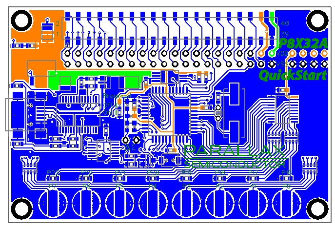
    Attached is my latest tweak. I dumped the SMT header and shifted things up. I had to move things around a bit in the upper left corner and fix a lot of traces/planes. Then, I simple duplicated the prop circuit rotated 180 degrees on the bottom to see how things would fit. I have a lot more tweaking to do, but obviously, it will be easy to get a dual prop layout done in this form factor.
  • ErNaErNa Posts: 1,742
    edited 2013-01-14 00:38
    Stacking boards seems to be a good idea to me. I found these connectors: http://www.gradconn.com/2-54mm/pdf/BB02-KS.pdf and understand that pins can be pushed in from both sides alternatively or long pins can be pushed through. That allows for flexible configuration of stacks. I can not guarantee that those are the right ones, but I know that they exist
  • jmgjmg Posts: 15,148
    edited 2013-01-14 01:17
    What should go in all that space?

    Crop lines.

    I've seen a few emulation boards now that have routed slots, and a trace-pair per web and the idea is you can break-off, or saw the board, into a much more compact engine

    The idea is to allow the smallest possible functional engine, and stuff like LEDs and Buttons and optional IO can go into the removable areas.
    In your case, the whole block may move to be more Header-aligned.
  • KeithEKeithE Posts: 957
    edited 2013-01-14 10:29
    dgately wrote: »
    Remember that the Raspberry Pi's GPIO is 5V-based...

    A link to the Raspberry Pi Wiki for the GPIO (note that it discusses Rev 1 & Rev 2 versions of the Raspberry Pi boards)...

    http://elinux.org/RPi_Low-level_peripherals

    dgately

    I'm pretty sure that the GPIO is 3V, and on the page you linked it states "GPIO voltage levels are 3.3 V and are not 5 V tolerant."
  • WBA ConsultingWBA Consulting Posts: 2,933
    edited 2013-01-15 00:17
    ErNa, Yes, that was one of my thoughts as well. At my last employer, we built several products for a company that made high end video equipment and they using the stacking connectors frequently. I also have always admired the PC104 stacking/pass-thru setup. Thanks for the link, I will keep that series of parts in mind. I think a pass thru design will enable some extra options.

    jmg, Interesting ideas. I have a capacitive touch demo board setup that way, but I never thought of using that in this case. It might be useful to make a 3"x3" board where 1"x3" is peripherals and when removed, leaves a Quickstart size board. I have a case in mind that would be perfect for a 3x3 PCB and it just so happens that the PCB Boss locations are 2.75" square which matches the distance between the holes on the 3" side of the Quickstart.
  • WBA ConsultingWBA Consulting Posts: 2,933
    edited 2013-01-15 00:54
    FYI: Here is the board layout in a cleaned up fashion. Once I add the mounting holes to the schematic so that the schematic perfectly matches the layout, I will post the DipTrace files. This layout provides the most real estate while adhering to as much as the original Quickstart form factor/layout as possible.
    694 x 476 - 46K
  • WBA ConsultingWBA Consulting Posts: 2,933
    edited 2013-01-31 00:57
    I realized that I forgot to update this thread with the DipTrace files once I had fixed the discrepancies between the schematic and layout. Attached is a zip file containing version 005 of what I have been calling the "Quickstart Origin". It is a clean version of the Quickstart design without any peripherals so if anyone wants to design a Quickstart based board, this would provide a clean place to begin, hence the suffix 'origin'.
  • cavelambcavelamb Posts: 720
    edited 2013-01-31 09:34
    What version of DipTrace should I install to try out.
    The freebie version refused to edit - over 300 pins.
  • WBA ConsultingWBA Consulting Posts: 2,933
    edited 2013-01-31 11:03
    This design only has 255 pins, but you may have to install the latest version since I am using DipTrace 2.3.0.1. I have the full version, but it should open in the free version as long as it is at least a 2.3 release. The latest version on the DipTrace site is 2.3.0.3, but I haven't upgraded to that yet.
  • MagIO2MagIO2 Posts: 2,243
    edited 2013-01-31 12:43
    Confirmed! I downloaded the latest free version and it works!

    WBA, thanks a lot for sharing this!!!!
  • User NameUser Name Posts: 1,451
    edited 2013-01-31 13:52
    What should go in all that space?

    What about an ARM Cortex M0 or M4F?

    Since potential customers may not want to bother with developing ARM code, you could create and burn a simple routine into the ARM that would have it function as a slave to the Prop, providing math coprocessing and ADC services. An M0 chip might cost as little as $1.26.
  • David BetzDavid Betz Posts: 14,511
    edited 2013-01-31 13:58
    User Name wrote: »
    What about an ARM Cortex M0 or M4F?

    Since potential customers may not want to bother with developing ARM code, you could create and burn a simple routine into the ARM that would have it function as a slave to the Prop, providing math coprocessing and ADC services. An M0 chip might cost as little as $1.26.
    Better would be to have the ARM act as the main CPU running the control code and use the Propeller for its "soft peripheral" capability. Then you get the best of both worlds!
Sign In or Register to comment.