Shop OBEX P1 Docs P2 Docs Learn Events
Controlling 2 servos with one pin using a transistor?? — Parallax Forums

Controlling 2 servos with one pin using a transistor??

kleekrukleekru Posts: 32
edited 2013-01-08 09:09 in BASIC Stamp
Is it possible to switch between two servos using a (or a couple) of transistors from one output pin?

I have basic servo control working but tried to use a transistor to switch the control of that servo on and off (from another pin)... and I cannot seem to do it.
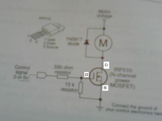
I'm using an IRF510 with the attached schematic (pardon the very poor quality photo).
Transistor switch.jpg


I would like to send a signal to the gate on the transistor to open the switch for a servo and then control the servo using a pwm pulse (from another pin).

I realize this will use 3 pins (one for each transistor) and one for the signal to the servos to switch between two servos but bear with me.

Thank you!!
Kevin
552 x 412 - 12K

Comments

  • Duane DegnDuane Degn Posts: 10,588
    edited 2013-01-05 10:29
    Do you want to control normal hobby servos or motors?

    You schematic is for controlling a motor not a servo. I'm pretty sure you can't control a hobby servo with the schematic you posted.

    There's also the question of why not just control the servo directly since it requires fewer pins to control them directly?

    The signal line to a servo does not require much current, there isn't an advantage to using a transistor (at least that I'm aware of).
  • ercoerco Posts: 20,256
    edited 2013-01-05 12:34
    I'm lazy; I wouldn't hesitate to drive 2 or 3 servos directly from one pin. Maybe a single series resistor, ~470 ohms, just in case I mess up on the connections. Who said a driver transistor was required? There's no significant current flow on a servo's control wire.
  • kleekrukleekru Posts: 32
    edited 2013-01-05 12:55
    I'm using standard parallax hobby servos. This is mostly an experiment but ultimately I would like to see if I can leverage the same output pin to switch between controlling two different servos. But I know this means using another pin to activate open and close the transistor. It is not required but I have another board (IOIO) that has a limited number of PWM outputs (9) and a larger number of digital outputs so I would like to see if I can control 12 servos (more than the board allows) with the pwm pins and switch between the extra servos using a transistor.

    I realize the schematic is for a motor but thought the concept would work through the ground for the servo to turn it on or off. Does that make sense?

    Kevin
  • Duane DegnDuane Degn Posts: 10,588
    edited 2013-01-05 13:20
    kleekru wrote: »
    Does that make sense?

    Much more than before.

    I'm still doubtful about the transistor idea. I'd think the overhead of switching the lines would be as much work as bit banging servo control from the other digital outputs.

    BTW, (Since you mentioned a different microcontroller first.) There is a microcontroller available that doesn't have any trouble with 32 servos.
  • jtbrownleejtbrownlee Posts: 9
    edited 2013-01-05 16:17
    Maybe you could use one pin to toggle a zone. Then you would only need pins for half the amount of servos plus one.
  • kleekrukleekru Posts: 32
    edited 2013-01-05 17:09
    Sorry, but I'm not clear what you mean by "toggle a zone". Can you explain more?
  • Mike GMike G Posts: 2,702
    edited 2013-01-05 19:11
    How about a J-K and two AND gates?
  • jtbrownleejtbrownlee Posts: 9
    edited 2013-01-05 20:06
    I have been using the propeller micro-controller and some of the objects that can control many servos will divide the servos into "zones". This staggers the pulses to the servos to reduce power surge. For example if you wanted to control 16 servos with 8 pins a 9th pin could be used to toggle the 8 pins between two groups of 8 servos. If you had a 20ms refresh one group could get there signal during the first 10ms then the zones would be toggled and the second group would receive their signal during the second 10ms then toggle and loop.

    I have never used a J-K. Where can you purchase these. I would like to read some datasheets.
  • ercoerco Posts: 20,256
    edited 2013-01-05 20:09
    Keep in mind that you must send a continuous pulse stream at ~50 hz to each servo in order to keep the servos working smoothly. Otherwise they shut down and may glitch when they receive the first pulse after a period much over 20 milliseconds.

    As far as multiplexing to save I/O pins, it would be possible to use 4 outputs to drive 8 servos using a 3-to-8 line decoder chip like a 74HC138. Video shows my board using 3 lines to select one of 7 LEDs or a piezo beeper (data line hardwired high here, so one of the 8 outputs is always on). To drive servos, your Stamp would use 3 lines to select which of 8 servos, then send the control pulse on the data/enable line. Note that a Stamp would be pretty busy just doing this, without a lot of extra time to process other data. But it does save 4 I/O lines, if that's what you're after. Likely more useful on a BS1 than a BS2 in this particular case.

    In similar fashion, you could use a 4-to-16 line decoder to drive 16 servos, like a 74HC154. Hmm. I might have to try this out myself!
  • Mike GMike G Posts: 2,702
    edited 2013-01-05 20:43
    I have never used a J-K. Where can you purchase these. I would like to read some datasheets.
    http://en.wikipedia.org/wiki/Flip-flop_%28electronics%29

    I suppose the JK could be replaced by an inverter. That would be 5 transistors and I'm pretty sure with a little thought the count could be reduced.
  • Beau SchwabeBeau Schwabe Posts: 6,559
    edited 2013-01-06 00:09
    Here is a little follow up on Mike G's suggestion of one J-K and two AND gates.

    This solution uses only one I/O pin to send a composite Servo pulse ... the J-K and the two NAND's break the composite pulse into two separate Servo Pulses. A simple RC timer is used to reset the J-K every 20ms to ensure that it will always start with Servo #1. This also allows a situation where if only one servo is addressed in the composite pulse then only the Servo #1 output is driven.
    1024 x 559 - 114K
  • kleekrukleekru Posts: 32
    edited 2013-01-06 01:37
    Thanks all! I'm happy to know there are some options but will likely need some additional help. The J-K solution looks very interesting although a little over my head. Do you have sample code as well that illustrates the pulses and looping required? How does this impact the performance/speed of the servos? I'll start reading what I can to understand why this would work... I think I get it but not well enough to implement myself.
  • jtbrownleejtbrownlee Posts: 9
    edited 2013-01-07 11:57
    Would it work if each pair of servos were connected with a PNP transistor and a NPN transistor. All the transistor gates connected to a common pin. When the common pin is high the NPN will conduct the signal and when low the PNP will conduct the signal.
  • ercoerco Posts: 20,256
    edited 2013-01-07 15:14
    jtbrownlee wrote: »
    Would it work if each pair of servos were connected with a PNP transistor and a NPN transistor. All the transistor gates connected to a common pin. When the common pin is high the NPN will conduct the signal and when low the PNP will conduct the signal.

    AFAIK, there's no configuration of that 2-transistor scenario which yields two "standard" pulse trains of 1-2 ms at 50 hz to keep the servos updated. At best, you could have accurate timing of either the high or low state with a pulsout, but the other state would be inaccurate and pick up all the overhead timing, so you couldn't time it to 2 uS or better accuracy.

    Even if you could toggle the pulsouts accurately, (high ~1.5 ms, low ~1.5 ms, repeat), that would give you an output frequency of ~333 hz, not the standard 50 hz. IIRC, servos vary, some are fine with higher frequencies, some are not and they are unstable.

    Another alternative would be driving the pin High-Z (essentially make it an input) for ~20 milliseconds so that neither transistor conducted, thus restoring the 50 hz drive frequency. It still comes down to timing the pulsouts properly and what works with your particular servo. Something like (untested):
    DO
    LOW 1           'make output, set low state
    PULSOUT 1,750   'send 1.5 ms high pulse
    HIGH 1          'change state to high
    PULSOUT 1,800   'send 1.6 ms low pulse
    INPUT 1         'make pin high z
    PAUSE 20
    LOOP
    

    Also, any of these options will consume more of your Stamp's overhead, all to save one I/O pin. What's that worth to you?
  • jtbrownleejtbrownlee Posts: 9
    edited 2013-01-07 16:23
    Im not sure if I understand how you got 333hz. If read correctly the two types of transistors can be used as normally closed or normaly open switches. If so I was thinking of this scenario.

    1. Update one servo
    2. Toggle transistors
    3. Wait 10ms
    4. Update second servo
    5. Toggle transistors
    6. Wait 10ms
    7. Loop

    This would give each servo 20ms refresh
  • ercoerco Posts: 20,256
    edited 2013-01-07 19:26
    If you just alternate high/low pulses of about 1.5 ms each, you end up with a "frequency" of 333 hz. Because with the simple 2-transistor circuit you describe, the low pulse starts at the end of the high pulse by definition. I suggested the high z state as a possible way to introduce a disconnected condition which might suffice for a 20 ms pause, or two 10 ms pauses as you wrote it.
  • kleekrukleekru Posts: 32
    edited 2013-01-07 21:12
    It sounds like most of the entries above are related to alternating the control of the servo. What if the transistor was used to open and close the supply circuit and both used the same control pin? Wouldn't that make things easier without needing to split the Pulsewidth within each cycle? I like the idea of using an NPN and a PNP transistor to toggle which servo is "active". It seems logical but I tend to miss something when I try this in practice. For example, I tried to simulate the circuit with an LED and it seemed to work at first but then the LED just stayed on after a short while with or without power to the base so I think I burned out the transistor (2N3904 NPN). Clearly I set this up beyond its rating... Hard for me to understand the limits based on the specs so I should study the basics a bit more. Any suggestions for a transistor that could handle the switching of a seperate 6v power supply... Also, does it make sense to control this transistor from a 3.3v output pin?
  • SapphireSapphire Posts: 496
    edited 2013-01-07 21:43
    What you are proposing is entirely possible. I have built a circuit where I use a transistor to cut the servo power when I don't need to move it to conserve battery power. I used a TIP120 NPN darlington power transistor, which can adequately handle the power to the servo. I drive the base from a 5v output through a 220 ohm resisor, and also have a 10k ohm resistor to ground, to make sure the transistor is off in case the output is floating. Your LED test should work, an LED isn't going to burn out a 2N3904 transistor, unless you didn't put a resistor in series with the LED. But a 2N3904 will burn up if you try to pass enough current through it to power a servo. The PNP version of the TIP120 is the TIP125.
  • ercoerco Posts: 20,256
    edited 2013-01-07 21:56
    You have plenty of interesting options to try now. I still say it that since microsecond precision is required on the pulse widths, it remains to be demonstrated which if any of these workarounds will deliver satisfactory performance and ultimately be preferable to using one pin per servo and/or using a dedicated servo controller. Did you mention which processor you plan to use?
  • kleekrukleekru Posts: 32
    edited 2013-01-07 22:13
    My prototype uses a BS2 with an SSC32 servo controller to drive 12 servos. But my next version will use the IOIO with a java program running on an android device over bluetooth to drive micro servos. However, the IOIO can only handle 9 pwm outputs and I need to drive 12 servos. Size is important so the SSC32 is bulkier than I want... I tried a TLC5940 pwm breakout board from Sparkfun but it is complex and requires latching in inverted pwm values... over my head for now. I only need to drive a maximum of 6 of the 12 servos at any point in time so it occurred to me, why can't I share pwm pins between 2 servos? Hence the questions above. However, it appears I'll need to create a board that has a number of transistors on it... which could end up taking up as much space as a well made servo board. I'm thinking about a relatively small one that allows 16 channel output from adafruit (http://www.adafruit.com/products/815)... which I think I will end up going with (once it is back in stock). Now I just need to learn how to program in Java to send signals to this board over the IOIO. I still may experiment with the transistor switching. The TIP120 and 125 suggestion sounds at least like it will be a learning experience and may help me start programming... it might even end up as a less expensive alternative over a fully built board.... This forum is great! I love all the quick responses and creative options. If I get this working, I will post results.

    By the way, I burned the heck out of my finger (blister and all) on an IRF510 MOSFET transistor trying to pull it out of my breadboard after it was attached to a 9V battery... just a warning for the kids out there that might be brighter than me to respect your electronics. ;)
  • ercoerco Posts: 20,256
    edited 2013-01-07 23:32
    Lucky you! Beau is making your request an open challenge, so everybody wins!

    http://forums.parallax.com/showthread.php/145218-Golf-Challenge-Controlling-2-servos-with-one-pin
  • kleekrukleekru Posts: 32
    edited 2013-01-08 01:01
    OK, I did it! Theory proves to work!! Sorry this is not on a propeller or BS2 but the concept should be portable to other microcontrollers leveraging just one pin with a PWM signal and multiple digital signals to toggle between servos. I suspect there are more graceful ways to do what I've done but I needed to use diodes to keep the current moving in the right direction. I posted a video to illustrate: http://youtu.be/oyPttj79Ip8. If anyone is interested in more details, let me know. I can probably put together a Fritzing view of the setup.
  • ercoerco Posts: 20,256
    edited 2013-01-08 09:09
    Very cool. Definitely post your schematic here and also in Beau's thread.
Sign In or Register to comment.