Shop OBEX P1 Docs P2 Docs Learn Events
Looking for chip — Parallax Forums

Looking for chip

teganburnsteganburns Posts: 134
edited 2013-01-04 17:23 in Propeller 1
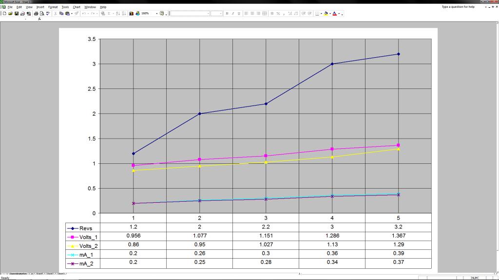
HI, I'm working on a project with the prop chip and my car. Obviously the chip can't handle 13v... but my other problem is that the speedometer has voltages as low as ~0.5v @ ~.11mA. My battery reading (for the car) was 12.85V @ 0.91mA So i don't know if there are any chips designed for this, or if anyone has any other ideas...? I added a Graph with my readings off the speedometer. But to clarify the speedometer is just the small end of the scale other parts have to deal with ~12V +
1024 x 576 - 62K

Comments

  • ElectricAyeElectricAye Posts: 4,561
    edited 2013-01-01 22:23
    Could you elaborate a little on what you're trying to do? Are you wanting to have the Propeller chip read your speedometer or...???
  • teganburnsteganburns Posts: 134
    edited 2013-01-01 22:26
    Yes, I want a chip that can read voltages between .11 and 13 v and communicate with the prop chip. Does that clear it up?
  • groggorygroggory Posts: 205
    edited 2013-01-01 22:57
    Set up an opamp in a non-inverting configuration set at a gain of around 1/5. Protect this circuit with perhaps a 15V zener and a static discharge circuit. Feed the output from that opamp into a standard ADC such as the MCP3202.

    That'll do ya.
  • teganburnsteganburns Posts: 134
    edited 2013-01-01 23:01
    groggory wrote: »
    Set up an opamp in a non-inverting configuration set at a gain of around 1/5. Protect this circuit with perhaps a 15V zener and a static discharge circuit. Feed the output from that opamp into a standard ADC such as the MCP3202.

    That'll do ya.

    Could you post some links please.I'm not too good with electronics.
  • kwinnkwinn Posts: 8,697
    edited 2013-01-02 00:13
    A simple voltage divider with an inductor and capacitor for noise filtering should be adequate to provide a 0 to 3.3V input to the ADC
  • rwgast_logicdesignrwgast_logicdesign Posts: 1,464
    edited 2013-01-02 00:21
    This method is WAY outside the box, as far as what your doing, but I think the best way to get your speed is going to be to tap the lines running to the cars motor control unit. If your running an obd2 system this should be very easy to figure out with some searching, and if your on odb1, you could look at car carker at gadgetgangster.com, it taps in to the cars computer and gets all kind of info, the car cracker is based on a propeller chip so it may be a simple matter of putting the code on your prop board and connecting some wires to the cars but.
  • Erik FriesenErik Friesen Posts: 1,071
    edited 2013-01-02 05:15
    The best way to do this is with a mid-high speed op amp set up with hysteresis(a little positive feedback) around the 2v mark, and gain around 2?. Most car speedo's are 0-5v output. If you use an op amp, you could hook into any magnetic type output as well.

    The problem with the obd2 approach is that the obd2 standard includes about 4 different ways of hardware interface, plus each manufacturer may have a different way of getting the speedo information out, because that isn't required in obd2, if I understand correctly. You'll note that some of the trip computers out there that use obd2 have a list of vehicles they work on, typically.
  • groggorygroggory Posts: 205
    edited 2013-01-02 12:57
    Just thought of another way...

    Take the initial signal and consider it dangerous because it's in an automotive environment.

    As such, throw some ESD protection and overvoltage protection in front of it

    then buffer it with a unity driver so you don't disturb any other electronics that are ahead of it

    Then put a resistor divider in front of that so it's down to a usable level (let's say 5 volt'ish)

    Then feed that usable level voltage into a voltage to frequency converter chip

    Then feed the output frequency from that chip into your propeller. Correlate frequency to speed. :-)

    I like this method...should allow you to calculate speed very quickly compared to precision ADC's.
  • pjvpjv Posts: 1,903
    edited 2013-01-02 13:15
    Hi Teganburns;

    I respect all the advice you have been given, but, depending on what other things you are wanting the projects prop to do, personally I would just do a sigma-delta software A/D converter inside the prop, and scale it for the voltage range you get from your spedometer (or is it tachometer since your graph shows RPM). The only parts you would need besides the basic Prop is two resistors and a 0.1 uf capacitor..... in all about 5 cents.extra.

    As an added bonus, in assembler the software to do this is likely much smaller and simpler than any software to "talk" to an external A/D chip.

    But you do need to understand how to accomplish this, and presuming you have some other applications for the Prop, I assume you are familiar with assembly programming.

    Your statement that you are not too good with electronics does concern me a bit.

    Cheers,

    Peter (pjv)
  • Erik FriesenErik Friesen Posts: 1,071
    edited 2013-01-02 13:20
    Just to clarify, my op amp idea would feed straight into a digital input. That is why the slew rate should be fairly fast. If you used a 1m 500K gain resistors, you'll never have to worry about attaching to any wire.
  • groggorygroggory Posts: 205
    edited 2013-01-02 14:58
    Just to clarify, my op amp idea would feed straight into a digital input. That is why the slew rate should be fairly fast. If you used a 1m 500K gain resistors, you'll never have to worry about attaching to any wire.

    If you are taking his signal which he defined as being 12V+ and put that into a non inverting opamp configuration with a gain of around 2, how would that solve things? How would that feed directly into the propeller? I'm confused.
  • Erik FriesenErik Friesen Posts: 1,071
    edited 2013-01-02 15:05
    My mistake. Gain resistors as stated are wrong. It would need to be calculated using positive feedback to create a Schmidt trigger. The alternative is using a regular Schmidt trigger, which may not have the input characteristics you want. However, vss signals can be a pain to deal with if you aren't using some type of hysteresis.
  • Duane C. JohnsonDuane C. Johnson Posts: 955
    edited 2013-01-02 15:13
    The delta sigma method is both accurate and fast. And no op-amps.

    Duane J
  • pedwardpedward Posts: 1,642
    edited 2013-01-03 19:57
    I think that you are missing some fundamentals. I haven't seen a speedo signal that is variable voltage, most often they are Variable Reluctance sensors, or Hall effect sensors.

    The VR sensors typically have 8 poles, some 4 poles, similar with Hall Effect sensors.

    The right off-the-shelf chip is the LM1815 for interfacing with a VRS sensor. Most auto manufacturers interface the sensor single ended, which kindof defeats the purpose of a floating sensor, but that's another thing...

    What make and model of automobile are you trying to interface the speed sensor on?
  • teganburnsteganburns Posts: 134
    edited 2013-01-03 23:53
    pedward wrote: »
    I think that you are missing some fundamentals. I haven't seen a speedo signal that is variable voltage, most often they are Variable Reluctance sensors, or Hall effect sensors.

    The VR sensors typically have 8 poles, some 4 poles, similar with Hall Effect sensors.

    The right off-the-shelf chip is the LM1815 for interfacing with a VRS sensor. Most auto manufacturers interface the sensor single ended, which kindof defeats the purpose of a floating sensor, but that's another thing...

    What make and model of automobile are you trying to interface the speed sensor on?
    Well if it helps at all my test points were right behind the speedometer module(as shown in the pictures) top arrow is (+) the bottom two are gnd. And it's a Toyoda Celica 1994. And I like the idea of programming the prop to read the obd, (less taking stuff apart/ complications) I would have to do more research on that though.
    1024 x 768 - 86K
    1024 x 768 - 84K
    1024 x 768 - 77K
  • groggorygroggory Posts: 205
    edited 2013-01-04 12:10
    teganburns wrote: »
    Well if it helps at all my test points were right behind the speedometer module(as shown in the pictures) top arrow is (+) the bottom two are gnd. And it's a Toyoda Celica 1994. And I like the idea of programming the prop to read the obd, (less taking stuff apart/ complications) I would have to do more research on that though.

    Ah, I see what's happening here...

    You should be reading the speedo signal itself. Aka, the signal coming off the sensor on top of the transmission that sends a digital signal where its frequency is proportional to speed.

    Instead, you are tapping into the signal that actually makes the speedometer needle move on the cluster.

    ..I would look into tapping into the speedo signal itself. It will be more accurate than pulling from ODB2. ODB2 has a delay to it and you can only sample so often. If you tap the sensor directly you can get the best data...and I don't think it should be too hard to tap that wire.
  • pedwardpedward Posts: 1,642
    edited 2013-01-04 17:23
    1994 is too early for OBD-II, so that's kinda off the table.

    Looking up your car, it has a 3 pin speed sensor, which means it's most likely a hall-effect sensor, which will give you a straight 12v (or 5v) on/off for each pulse. I seem to recall many manufacturers setup the gearing of the sensor to generate 2000 pulses per mile, or some derivative thereof.

    I would get a wiring diagram for your car, find where that output goes, then use a resistor to drop the signal, probably safe to start with a 22k, to read on a Prop input. You might want to try the Propeller scope firmware to play with the signals.

    The "right" way to interface such a signal would be to use a 4N25 optoisolator to separate the prop, but a resistor will probably work for your needs.
Sign In or Register to comment.