

Large messageboard
 Tumbler
Posts: 323
Tumbler
Posts: 323
Hi,
I need to control a large messageboard (12 x 16 segments)
Each display consists about 4 m ledstrip (12V) Total power is about 5W per display.
and i have some questions.
1: I want to control it with 24 shiftregisters 74595, so i need to send 192 bits into the modules.
Would it to slow for this?
2: I'm not a datsheet expert, but it seems that the 2803 can handle 500mA per channel? or is this the total power per chip (8 channels)?
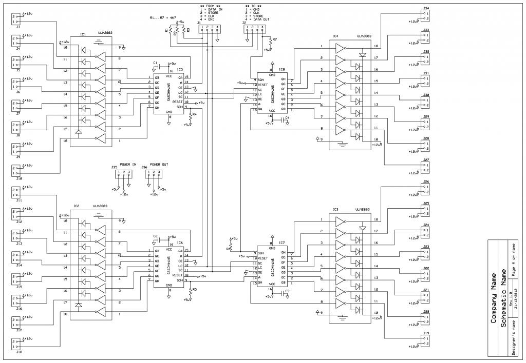
Attached a picture for what i have now (for 2 displays), so i need 6 of them
.
I need to control a large messageboard (12 x 16 segments)
Each display consists about 4 m ledstrip (12V) Total power is about 5W per display.
and i have some questions.
1: I want to control it with 24 shiftregisters 74595, so i need to send 192 bits into the modules.
Would it to slow for this?
2: I'm not a datsheet expert, but it seems that the 2803 can handle 500mA per channel? or is this the total power per chip (8 channels)?
Attached a picture for what i have now (for 2 displays), so i need 6 of them
.

725 x 79 - 24K

1024 x 708 - 100K
Comments
Think that'll do what you need? It'll be a lot of parts, but I can't think of any small/simple way to do what you are trying to do.
If you want, let me know how you connect to the displays, and I can build a board layout for you. They shouldn't cost more than $100 for all the PCBs for all 12 segments (from OSHPark), unless you want the board to cover the whole back of the display.
No, that is not the case; it can handle 500mA if only one channel is operating. The load goes down to about 125mA with all eight operating.
The TPIC6B595, on the other hand, behaves just like a shift register and has open-drain outputs capable of sinking 350mA each, and all eight outputs may operate at the same time.
If that's not enough current then I suggest you use 74x595s with outputs connected to the base of a TIP12x (one per output) through a 1K resistor. Inexpensive and gets you a lot of current (TIP120 is rated for 5A @ 60V). Assuming your displays are common cathode, use the TIP125 (PNP) for the anode side, and the TIP120 (NPN) for the cathode side. Multiplexing the display with a PASM cog would be quite easy and would cut you down to four shift registers per display.
I'm using TPIC6B595s. So far, I've cascaded six of the 595 chips. I had to give up on 24-bit color (too much flicker), but 15-bit color works fine.
I'm using 754410 h-bridge chips to drive the anodes since I had some on hand. I think I'll check out the TIP125s Jon suggested.
Do you need bightness control? And if so how much? (This is what will determine how many 595 chips you can chain together.)
For lots of LEDs you can use multiple data lines but still have all the shift registers share the clock and latch lines.
Is this a module with drivers on the back allready?
If so data-sheet for it is?
Is a display a module of 12 letters? or is a display one letter?
12letters*16seg= 192 Leds (or clusters of LEDs) that need to be controlled.
Did you draw the schematics or is that from the LED module manufacture?
It uses regular HC with 5v Pull-up, not sure if that is a good match with Prop.
though protection diodes should kick-in and 4.7K will throttle current.
A HCT could be powered by 5V and still detect 3.2V as a high.
A AHC would handle up to 7V, but high signal needs to be at least 0.7*Vcc
Where is the second "16" coming from? I thought 196 was the LED count?
And if a VGA monitor would be cheaper is besides the point. LEDs are just cooler! (I think I may be preaching to the choir here.)
That reminds me, the TPIC6B595s have a 0.85*Vcc logic level requirement in the datasheet. I've used TPIC6B595 in several Propeller projects and they have always worked fine with 3.3V logic (at 5V Vcc). But if you need to be safe (not for your own use) you may want to use level shifters.
driver chip is recommended to stop the rail drooping.
How physically large is the message board? Logic signals don't travel very far without issues of crosstalk and reflection...
I will take Jon's TPIC, but not the B-version of it.
I don't know where you get the 350mA from. I couldn't find it in the datasheet.
I found a better one, the TPIC6595, wich can handle a countinuous drain current of 250 mA.
Taking ledstrips of 24V will reduce the current to max 120mA per segment (in my example)
@Tony, image is not a module, it's just a selfmade one
You can have the source file if you want
I will update the schematic later today and post it here.
And before i forget, Happy Newyear everyone!
Are the pull up resistors ok here or do i use other resistors for each IC?
And what about the NC connections, should i ground them?
attached the expess pcb schematic file
Attachment not found.
Is each letter a module?, or did you even make the LED letters by yourself?
Do you have data-sheet for LED letter?