Shop OBEX P1 Docs P2 Docs Learn Events
Trying to get serial RFID Read/Write Module to work with Realterm — Parallax Forums

Trying to get serial RFID Read/Write Module to work with Realterm

queenbeequeenbee Posts: 3
edited 2013-01-02 10:46 in Accessories
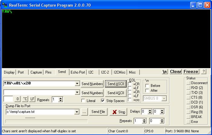
Hi, I just got my RFID Read/Write Module a few days ago and I am trying to get it to work with Realterm. When trying to read the tag's serial number, the command to send is !RW\x01\x20. But the module green light is always on and never turns red.

I have yet to get any response from the module, perhaps the module is faulty?

Can anyone give me some help on how I can check if the module is OK? How can I do some tag reading test using Realterm?

Thanks.

realterm_RFID.JPG
702 x 446 - 54K

Comments

  • FranklinFranklin Posts: 4,747
    edited 2012-12-25 18:54
    How are you connecting it to your computer and are you sure you are connected to the right com port in realterm?
    Communication: asynchronous serial 9600 bps,
    (8N1); 5 V TTL-level, non-inverted
  • kwinnkwinn Posts: 8,697
    edited 2012-12-25 19:21
    To work with a PC serial port or USB/serial port connection you will need an RS232 driver between the RFID unit and the serial connector to convert the RFID unit TTL levels (0-5V) to the RS232 levels (between +-3V to +-12V). The com port on the PC should be set to 9600 baud, 8 data bits, no parity, 1 stop bit.
  • queenbeequeenbee Posts: 3
    edited 2012-12-25 19:32
    I am using a ATEN USB to RS232 converter and connect the TX(3) and RX(2) pin to the SN and SOUT pins on the RFID module respectively, GND(5) on the RS232 is connected to the GND pin on the RFID module. Is that OK?

    The port setting on Realterm is as attached.

    Thanks.

    rfid_realterm2.JPG
    701 x 448 - 45K
  • kwinnkwinn Posts: 8,697
    edited 2012-12-25 19:50
    No. The RFID unit needs TTL levels. RS232 levels are anywhere from +-3 to +-12 volts. This could cause damage to the reader/writer. It also needs to be polled continuously. When you send a read command it turns the unit on, tries to read a card, turns off, and sends back the card data or an error message if no card was read.
  • Chris SavageChris Savage Parallax Engineering Posts: 14,406
    edited 2012-12-28 16:00
    Besides causing potential damage to the RFID R/W Module, the signals are inverted from the RS-232 port, whereas the RFID R/W Module requires non-inverted TTL signals. That said, it is unlikely you're sending the correct stream of data to the RFID R/W Module to initiate the read. The sequence of bytes is very specific in order to initiate a read. If no tag is at the reader during the read an error code will be returned. I created a VB app that lets you read tags from the reader and I used my Saleae Logic Analyzer to show the sequence of bytes coming/going. If you like I can post that information.
  • 4x5n4x5n Posts: 745
    edited 2012-12-28 20:40
    Besides causing potential damage to the RFID R/W Module, the signals are inverted from the RS-232 port, whereas the RFID R/W Module requires non-inverted TTL signals. That said, it is unlikely you're sending the correct stream of data to the RFID R/W Module to initiate the read. The sequence of bytes is very specific in order to initiate a read. If no tag is at the reader during the read an error code will be returned. I created a VB app that lets you read tags from the reader and I used my Saleae Logic Analyzer to show the sequence of bytes coming/going. If you like I can post that information.

    Glad to hear you confirm what I found via experiment that the read/write module doesn't wait for the presence of a card but returns virtually instantly if a card isn't present. I wish that the error code and documentation was more clear about it's action when a command is issued with a card present.
  • kwinnkwinn Posts: 8,697
    edited 2012-12-30 01:25
    I know the data sheet is not great, and does not explicitly state that the card has to be near the card reader when a read command is issued but the information is there if one reads the data sheet carefully.

    Page 3 covers the operation and communications protocol pretty well although it would have been nice if they had explicitly stated that a card had to be near the reader when a read or write command is executed.

    Pages 4 and 5 have code examples for the commands but again they do not provide any more information than how to send the command and receive the status.

    Page 6 lists the returned status codes, and under the “Error Checking” paragraph states that “In most standard implementations, the user will repeatedly call the desired function until the ERR_OK status byte is returned, indicating that the function successfully completed with no errors.”

    A sample program outlining the loop to poll the card reader along with a comment as to the action to be taken when a valid card is read would have been of help.
  • 4x5n4x5n Posts: 745
    edited 2012-12-30 11:21
    I agree that the docs hint at needing a card in range when sending the read but never actually says it. Even the error code that the module returns isn't clear that the error is the result of a card not being in range.

    I'm not complaining mind you because it is easy to test and find out for sure. I've also seen worse documentation for hardware in my life. I just think it would be nice for the documentation be a little clearer.
  • Chris SavageChris Savage Parallax Engineering Posts: 14,406
    edited 2012-12-30 20:46
    Your feedback does not fall on deaf ears. This product should definitely be reviewed to see if we can improve the overall experience for the customer. As the new year rings in we'll be looking at many products to see what improvements we can make to improve products, documentation and examples for the customer. Don't be afraid to let us know if you feel we're not providing adequate information, since if you're feeling that way, it stands to reason other customers may be equally as confused.
  • 4x5n4x5n Posts: 745
    edited 2012-12-31 13:30
    Chris, Thanks for your quick response. As always Parallax sets the standard in responsiveness to customers!
  • Chris SavageChris Savage Parallax Engineering Posts: 14,406
    edited 2012-12-31 14:01
    Thank you, and check out the blog entry I just posted. It has some realy useful information for trying to use the RFID R/W Module with a PC.
  • queenbeequeenbee Posts: 3
    edited 2013-01-02 00:40
    Hi Chris,
    Thank for the blog entry which provides additional information on the interface with the RFID read/write module.

    I have also ordered the RFID read only module and will be receiving the shipment soon.

    For the read only module, is the level translator required for the interface with a PC RS232 port?

    Thanks.
  • Chris SavageChris Savage Parallax Engineering Posts: 14,406
    edited 2013-01-02 10:46
    Yes, both RFID Modules work with TTL level logic signals by default. To interface either to the PC you would need the RS-232 circuit. However, the RFID Reader has an enable line, so the circuit is wired slightly different. For more information please see the following link. http://forums.parallax.com/showthread.php?103732-RFID-Reader-Software-(VB.NET)&p=727719#post727719

    In that thread there is a link to the schematics page as well. I hope this helps.
Sign In or Register to comment.