Is it OK to mount inductors next to each other?
 rwgast_logicdesign
Posts: 1,464
[FONT=arial, sans-serif]So i was adding just about finished with the first rail of my switching power supply when something very important hit me, i might be laying out my inductors wrong! The circuit calls for a 330uH and 20uH inductor. The 20uH is an optional ripple filter. Ive already mounted the 330uh inductor standing straight up like an electrolytic cap, i had planned on mounting the 20uH the same way directly next to it.. The board will have 3 sets of inductors like this maybe a quarter inch from each other. Is this bad? [/FONT]
[FONT=arial, sans-serif]My layout has all the components so close there touching because i need to fit the board in a tight space and I'm trying to keep the components as close to the buck regulator chip as possible to reduce any Johnson noise or lead capacitance as per the data sheet.[/FONT]n[FONT=arial, sans-serif]Ive read it's a good idea to flip the axis of inductors at 90 degrees from each other. Im guessing that means the 20uH inductor should have its leads bent 90 degrees and be laying on its side, but that will add size the the board..
This is the data sheet to the inductors im using, they are the IHB-1 series. Before anyone brings it up I know my 20uH inductor is un-necessarily oversized, I sisnt realize it was rated at 9 amps I thought the whole IHB-1 line was 1600mA not just the 330uH. I dont see anything about wether these inductors are sheilded, have full magnet cores etc..[/FONT]
http://www.google.com/url?sa=t&source=web&cd=1&ved=0CDoQFjAA&url=http%3A%2F%2Fwww.vishay.com%2Fdocs%2F34015%2Fihb.pdf&ei=6abUUKz8HOb-2QXXm4HQCA&usg=AFQjCNFQDjIpkGh0aEdej4MF5dU8_LkTYg&sig2=bVxgE_f_ie2Kd26ivdB8tQ
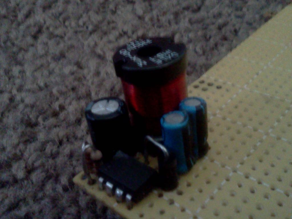
Here is a picture of what I have soldered and glued so far, it is a 5v rail without the ripple filter

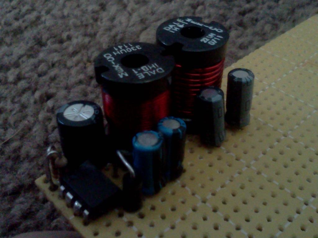
This is a picture of how I planned to mount the ripple filter circuit

I has planned on building 2 more circuits identical to this one (except the programming resistors) side by side, as close as possible. Then when I looked at what I was doing I realized inductors will induct, and could possibly cause induction between each other. Each inductor will have 500mA running through it at 5v or 3.3v, so its not like there a high amount of wattage on the coils, maybe that will make a difference too?
[FONT=arial, sans-serif]My layout has all the components so close there touching because i need to fit the board in a tight space and I'm trying to keep the components as close to the buck regulator chip as possible to reduce any Johnson noise or lead capacitance as per the data sheet.[/FONT]n[FONT=arial, sans-serif]Ive read it's a good idea to flip the axis of inductors at 90 degrees from each other. Im guessing that means the 20uH inductor should have its leads bent 90 degrees and be laying on its side, but that will add size the the board..
This is the data sheet to the inductors im using, they are the IHB-1 series. Before anyone brings it up I know my 20uH inductor is un-necessarily oversized, I sisnt realize it was rated at 9 amps I thought the whole IHB-1 line was 1600mA not just the 330uH. I dont see anything about wether these inductors are sheilded, have full magnet cores etc..[/FONT]
http://www.google.com/url?sa=t&source=web&cd=1&ved=0CDoQFjAA&url=http%3A%2F%2Fwww.vishay.com%2Fdocs%2F34015%2Fihb.pdf&ei=6abUUKz8HOb-2QXXm4HQCA&usg=AFQjCNFQDjIpkGh0aEdej4MF5dU8_LkTYg&sig2=bVxgE_f_ie2Kd26ivdB8tQ
Here is a picture of what I have soldered and glued so far, it is a 5v rail without the ripple filter

This is a picture of how I planned to mount the ripple filter circuit

I has planned on building 2 more circuits identical to this one (except the programming resistors) side by side, as close as possible. Then when I looked at what I was doing I realized inductors will induct, and could possibly cause induction between each other. Each inductor will have 500mA running through it at 5v or 3.3v, so its not like there a high amount of wattage on the coils, maybe that will make a difference too?


Comments
The simple answer is yes it can be a problem sometimes.
The inductors your using look like the magnetic field is not "Closed" as in a toroid or cup core.
So the fields can interact somewhat.
You really must mock this up to see if there is a problem.
I like to use a sheet of PC board as a ground plane and cobble the circuit on it sort of freeform. (Looks really ugly but effective.)
This way you see if there is a problem and change the orientations of the parts before committing to a real board.
One fix is to mount them at cross planes or 90 degrees to each other.
Or choose a toroid which is often smaller than the open field type and the field is much more contained.
Or a cup core but these are generally expensive.
Duane J
Also I mentioned the 90 degree thing above but i cant seem to find pictures of it. Does this mean I place the leads of the second inductor at a 90 degree angle from the first or do I lay one inductor on its side i.e bend the leads 90 degrees and stand the other straight?
I see the other inductor looks like it has fat high current wire. But the 330uH one looks like it is thin wire?
How many amps is it rated for?
It might be an interesting experiment to set them up in the same relative positions as your board and drive a signal into one and see what comes out the other.
Orienting them at 90 degrees to each other will minimize coupling.
If you are really keen you could model your power supply in Spice. You can set the degree of coupling between inductors in Spice.
I like to play with LTSpice from Linear Technology which is free and easy to use. LTSpice is exactly intended as a tool to model switching supplies although it works very well as a general circuit simulator as well.
magnetic behaviour changes a lot with temperature, air has very precise magnetic properties). Adding a gap increases the current
before magnetic saturation appreciably and allows more energy to be stored in the magnetic field (actually its mainly stored in the field
in the gap!)
If you want to place inductors close together or close to other components without de-tuning then go for cores with an internal gap rather than these
open-bobbin style ones. For instance these have the gap at the top, fringe fields of limited size:
http://uk.farnell.com/te-connectivity-sigma-inductors/3631b101ll/choke-smd-shielded-100uh/dp/1174029
Transformers are a different case - the exact value of inductance doesn't matter and you don't want to store energy, so gapless
magnetic circuit is the normal arrangement there.
Please give us some references where we can learn more about this Air Gap theory.
Thanks!
Duane J
Your inductors are radial, if the where axial you could do a 90 degree orientation.
The issue is that you want the axis about which the inductor is wound to be 90 degrees from that of the other inductor.
Since your inductuctors have that axis normal (pointing out of) to the circuit board, changing the position on the board or rotating the inductors footprint doesn't change that relationship.
If the inductors where axial mounted (the magnetic axis parallel to the circuit board) then rotating the footprint of one of the inductors by 90 degrees would achieve the desired result.
C.W.
Note: You *could* lay one of the inductors that you have on it's side and use epoxy or something like that to hold it in place.
http://www.kickstarter.com/projects/412473553/opengrab-open-hardware-electro-permanent-cargo-gri
I don't know anything about inductors and air gaps, but it sure looks cool
Anyways back on topic, I have tested this thing with the filter inductor right next to the main inductor with no issues I can see... When I test the circuit using one inductor I read 5.06v on the output, when I inserted he 20uH in to the board and and soldered a piece of wire on from the main output to the input of the 20uH I still got a reading of 5.06v. So theres not transformer effect going on here, but that doesn't mean theres not a bunch of noise from cross induction between the coils. I have ordered a PropScope and will just wait till it gets here to view the signal, and see whats actually going on. Could I maybe wrap the coils in tape and then foil and then tape again to shield them if I end up seeing a ton of noise? If I have too I can just stick the filtering circuits on the actual boards that need the extra filering, instead of in the power supply. Im surprised the data sheet doesnt talk much about the layout of the filter circuit in relation to the main switching supply.
in reference to your story, that was capacitive coupling, not inductance.
remember that two conductors or conductive surfaces running parallel to each other with some sort of non-conductive gap between them forms a capacitor.
lives on the surface of insulators and completely isolated conductors only. Could well be an inductive spike from
something though.
Your inductors are probably working at very different frequencies helping to prevent problems with mutual inductance?
Careful about wrapping conductors around a bare coil like that - you might create a short-circuit single-turn link, or at
least increase losses through eddy currents if the foil is in a high-magnetic field zone.
Your layout looks good. Yes, the simple test would be to test with an ADC.
What you can do is to wrap the coil and leave a gap so there will be no shorted turn.
Duane J