

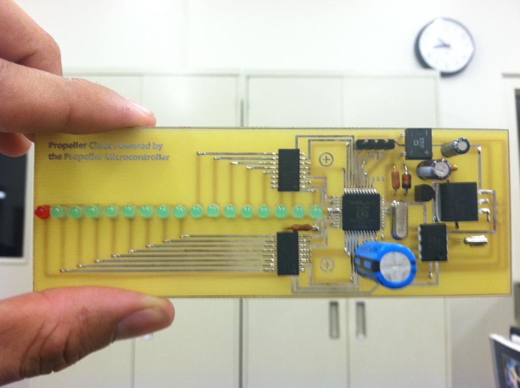
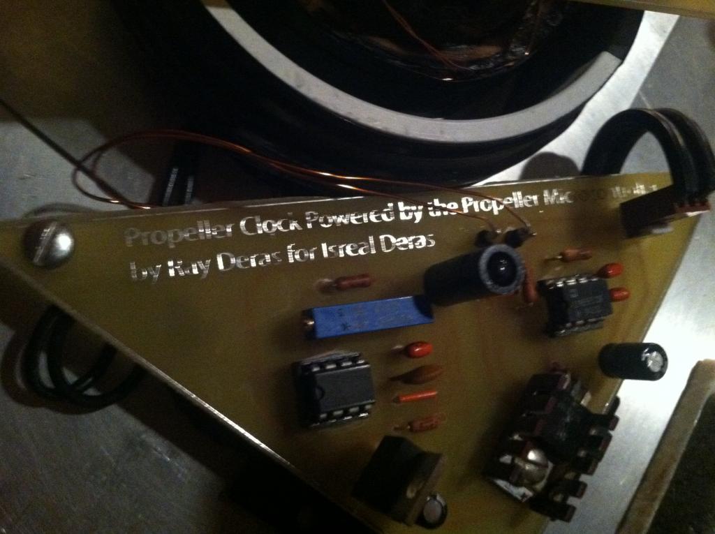
Propeller Clock Powered by the Propeller Microcontroller

Here is my entry to the "Hack the Halls!" contest. I started making this out for my brother and when I saw the contest I figured I'll post and see how I do. Check out the video:
http://www.youtube.com/watch?v=hSxGq68Pllk
It was supposed to be a simple project to help me get better with using the Propeller microcontroller but it turned out to be a great challenge. Here's a short summary of the components:
Let me know what you think.


http://www.youtube.com/watch?v=hSxGq68Pllk
It was supposed to be a simple project to help me get better with using the Propeller microcontroller but it turned out to be a great challenge. Here's a short summary of the components:
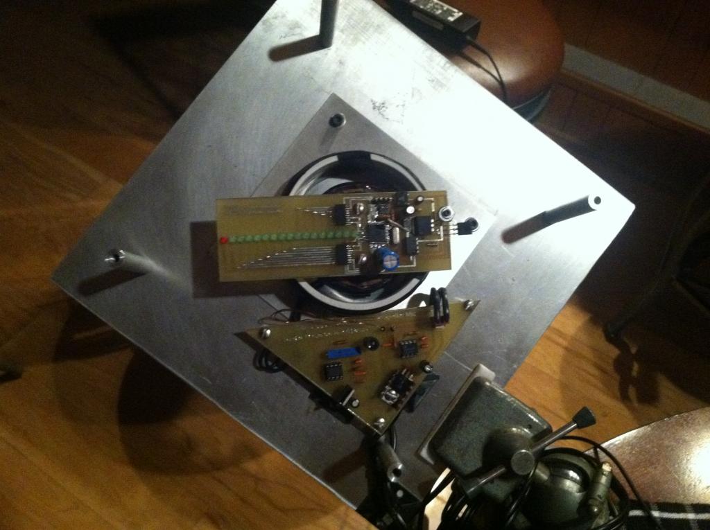
- A 555 timer generates an AC signal to a power MOSFET to deliver current through the primary coils of an air core transformer to get power to the rotating propeller.
- the secondary coil (attached to the rotating propeller) picks up the AC signal.
- The AC signal goes through some circuitry (see attached schematic) to get a 3.3V to power the components on the propeller.
- a 2nd 555 timer generates a ~38KHz signal to the IR LED
- an IR detector at the propeller picks up the IR signal for reference.
- a DS1302 was used to keep track of the time
Let me know what you think.
1024 x 765 - 81K
1024 x 765 - 104K

1024 x 765 - 64K

1024 x 765 - 87K

Comments
To be elegible for the contest, don't forget to provide a link in the Hack The Halls thread: http://forums.parallax.com/showthread.php?144156-CONTEST-Hack-The-Halls!
That's just too cool for words! Good luck with the contest and to your brother! I hope he has a full and complete recovery.
-Phil
Also, I didn't give credit to those that are due. I picked up some ideas from "Tjaco's design graveyard" where he has a schematic of a propeller clock he built. Also, thanks to Steve Augsberger who gave me some insignt on filtering out the AC signal being picked up by the secondary coil.
I'm pretty sure the "gauge" in this case is the American Wire Gauge. You can find a conversion table in this Wikipedia article.
I know the convertion, but we'll get the inaccuracy. That mean maybe the Emitter and Receiver have different frequency and they can't work. Do you think so?
I hope others will correct me if I'm wrong but I don't think the gauge is very important. You just need to make sure the wire is large enough so the resistance isn't too high. I think the important figure is the number of turns used in the coil. I think if you use wire that's thicker than what Ray_D used, it shouldn't be a problem.
If there is some inaccuracy converting AWG to MM wire sizes, choose the MM wire size that is larger than, but as close as possible to the AWG size.