

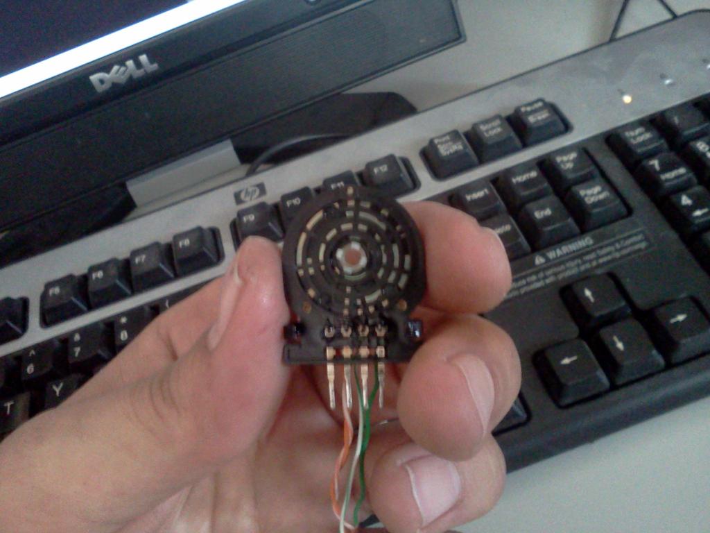
Has anyone ever seen one of these? Three channel "Rotary Encoder" from a VCR's PCB.
 rwgast_logicdesign
Posts: 1,464
rwgast_logicdesign
Posts: 1,464
So last night I was just scrapping parts, specifically input devices for a controller. Walked away with a few joysticks and rotary encoders. I ended up desoldering something I thought was a rotary encoder but im not so sure what it actually is. It came out of a VCR I think, and the pins were labled ground, Channel A, Channel B, and Channel C. I thought it was strange there was no power pin labeled. I brought it in hooked it up to a logic analyzer and couldn't get it to work, It seems as though anywhere I connect power to it causes it to short out the supply when I turn the knob! I then looked at the back and saw the crazy design on each of the three channels, realizing it wasnt just a quadrature encoder with a weird pin label I thought Id ask if anyone has seen one before, and if so why would it be on the PCB of a VCR?! It wasn't mounted in a way where the user could turn it, im not sure maybe the motor use to turn this device or something.. Hope I can someone can tell me how it works and maybe I can come up with a use for it sense I took time out of my night to de-solder it, lol.

I also pulled a mechanical quadrature encoder from a mouse wheel and some joysticks off an x-box controller, should all this stuff be mostly compatible with the parallax code for there joystick and rotary encoder?
I also pulled a mechanical quadrature encoder from a mouse wheel and some joysticks off an x-box controller, should all this stuff be mostly compatible with the parallax code for there joystick and rotary encoder?

1024 x 768 - 80K

1024 x 768 - 90K
Comments
Many manufacturers went to this when they started using a single "mode" motor to operate the loading, unloading, FF, REW & Play functions. It would indicate when the mechanical parts are in their correct position.
John Abshier
Just my .02...
Edit: The only potentially bad thing might be any dirt or poor connection of the switch contacts you'll get some glitches in your traces.