Boosting the current of a switching regulator, using a transistor?
 rwgast_logicdesign
Posts: 1,464
Ok ive been trying to figure out exactly how I intend to build the DC to DC power system for my robot. From the beginning Ive planned on using switching regulation with filters, the regulators Ive picked are LM2574AN, by recommendation of Dr-Acula. These things are very nice and very simple to set up, im getting a quiescent current of about 2 micro amps using them, thats awesome! I must say im very happy with the chip over all. The only issue I have is there only 500mA output, Id really like to have one of my 5v rails be capable of about an amp 2 would be better, but probably not necessary. I did some reading and apparently switching regulators have the same issue as LDO's as far not being able to connect there outputs in parallel.
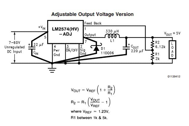
Im using the adjustable version of the LM2574AN, this is the simple schematic from the data sheet to get 5v regulation, this doesnt include the filter:

Anyways I was rooting around through bags of junk/surplus and found a few TO-220's labeled P32A im betting these are tip32a power transistors http://www.onsemi.com/pub_link/Collateral/TIP31A-D.PDF I was wondering if maybe there was a way I could set the regulator high enough to compensate for the transistors voltage drop, then run the output from the regulator to the transistor(s base I would think) and the p32a would be able to boost my current and pulse on and off with the regulator. Im sorry im transistor stupid I wouldnt even know how to bias the thing to output an amp or two, or if this would take way more power than just using a 1amp LDO instead.
Im using the adjustable version of the LM2574AN, this is the simple schematic from the data sheet to get 5v regulation, this doesnt include the filter:

Anyways I was rooting around through bags of junk/surplus and found a few TO-220's labeled P32A im betting these are tip32a power transistors http://www.onsemi.com/pub_link/Collateral/TIP31A-D.PDF I was wondering if maybe there was a way I could set the regulator high enough to compensate for the transistors voltage drop, then run the output from the regulator to the transistor(s base I would think) and the p32a would be able to boost my current and pulse on and off with the regulator. Im sorry im transistor stupid I wouldnt even know how to bias the thing to output an amp or two, or if this would take way more power than just using a 1amp LDO instead.


Comments
There are 3V, 5V and adjustable ones. You will need a higher current diode (as per the spec sheet) and also the inductor is 100uH and will need to be rated for as many amps as you need.
Not sure about transistors. And your TIP32 is a PNP. Lots of circuits out there using a standard 7805 and a power NPN transistor.
Then there are other ways of looking at things. eg for motors and servos often you don't need regulated voltages. eg for servos, the standard supply is 4 nicads. The only regulation you need is for the controlling electronics. You can do the same thing with motors. In the olden days I remember pulling apart radio controlled cars and they often had a 9V battery for the receiver electronics and four large batteries for the motor.
So maybe you don't need a power regulator after all?
It may be better anyway for noise reasons to have separate motor and control regulators?
I started buying one or two of those regulators. I now buy them in batches of 10 or so!
www.ebay.com/itm/1pcs-DC-DC-Buck-Converter-Step-Down-Module-LM2596-Power-Supply-Output-1-23V-30V-/251066005460
If you need to step up the voltage you could look at this:
www.ebay.com/itm/261096788682
I just used one of the Step up modules on a project and it worked out well.
Do you know if these ebay modules include a filtering circuit? I can only see one inductor, I know this is also using an lm54xx, so id think it would also require a second inductor for the filter. My biggest fear is causing noise issue on my ADCs. I guess it would still be cheaper to just filter this module than to build one with a filted.
its weird no one chimed in on the transistor thing. I would think a transistor switching on and off in sync with the regultor and amplifying the current would be a common scenario. Seems like a transistors perfect for this job!
You can't build them for that price, at least in small qty.
If you look closely at the picture it shows there are two large surface mount capacitors (silver cans) on board so they have some filtering. Exactly how well they filter you would need to check on a scope to be sure. You could always add additional caps if needed,
Have you considered using a different regulator all together or do you want to just add a circuit?