

The very originally named Ro-B-oT, or robs robot!
 rwgast_logicdesign
Posts: 1,464
rwgast_logicdesign
Posts: 1,464
Ok I figured I would start a real thread on this guy now that its starting to get somewhere, just signed up for a YouTube account so I can show it off a little!
So here is the what im trying to accomplish in the short run, as far as design goes.
There is going to be a brain made from one or two propeller chips, just depending on how many cogs I need in the end. The robot also uses an Arduino that is dedicated to a few mundane tasks, which are generating 32Khz PWM to controll the H-Bridge, reading the motor encoders and implementing a PID algorithm to keep the wheels at the same speed, the last tasks of the Arduino is power management and battery charging. The idea is to make a board with a pre Arduino loaded Atmega168 connected to an STM l6205 H-bridge, the motor encoders, and the power system/batterys. This board will then communicate with the propeller via Uart . This makes life a bit easy, after the propeller makes a decision based on sensor inputs it just send a serial command to the Arduino with the motors direction, speed and angle.
So far what I have implemented are a few open loop motor functions, along with serial control on the Arduino. Right now im working on the power system hardware and the motor encoders code.
At this point Ro-B-oT will will be powered by 16 (19.2v) 2450maH NimH Duracell batteries. This will allow a full 18v to the motors after the voltage drop on the H-Bridge. All 5v and 3.3v power rails will be supplied with LM2547N-ADJ switching regulators, along with the recommended noise filtering circuit.
As far as sensors and features (not saying all use them all, just things at my disposal to make my bot smart) for the propeller right now I have,
1 Serial over BT
1 WizNet along with a wifi to ethernet box
1 SD Breakout
1 USB Host
1 Memsic Dual Access Acceloremeter
1 Analog devices 3 Access Acceloremeter
1 HMC5883l Compass/Magnometer
2 WiiMote Cameras
8 Red Lasers
6 DS1620 thermometers
5 Sonar modules
3 CDS PhotoResitors
25 Bumper switches, thank you OBC for selling these a 1 cent a pop")
Various IR LEDs from huge to narrow viewing angles, A bunch of 38Khz receivers, along with Reflective and Interrupt IR sensors
So overall that stuff should hopefully be a great start as far as getting some really good object detection and telemetry stuff going, along with data loging and wireless communication. As far as future plans I want to make the bot AW4WD, just need to source some erector pieces, and id like to add a rasbery PI with the camera module to do machine vision and speech/speech recognition. Like I said that stuff in the list will probably keep me on my toes for a bit, along with designing a nice remote.
So lets get to the GOOD STUFF, pics and video!!
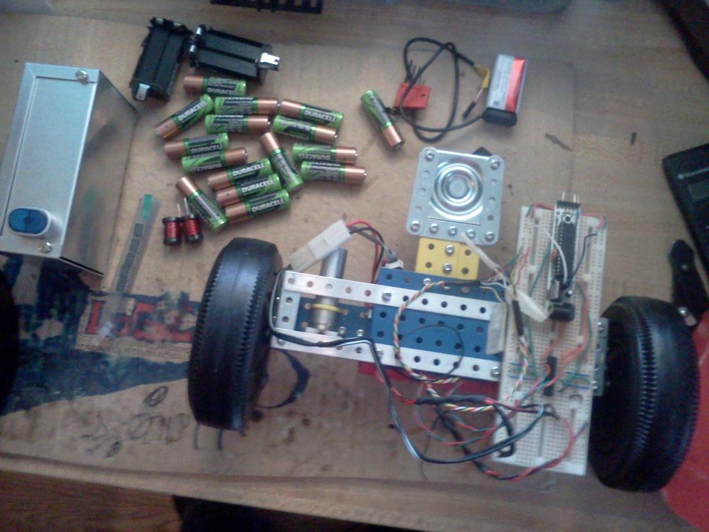
So this is the bot as of 12/13/12, All the stuff around it plus the circuitry on top of it will all be encased in the aluminium enclosure, This will be the power/motor control part of the bot.
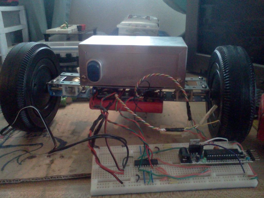
This is Just showing what I hope it will kind of look like soon!
Now here is a video of a test run. The video shows the bot using open loop functions to go forward, brake, go backward, not to smart yet but the propeller will fix that

Now that you guys have seen this in action maybe someone can tell me why the robot goes fairly straight when the caster wheel is in front, but when I let the caster wheel trail, it is anything but straight!!!! I know encoders and a PID loop will fix this, but id like to get the thing going pretty straight before relying on PID, im not trying to slow my bot way down!
So here is the what im trying to accomplish in the short run, as far as design goes.
There is going to be a brain made from one or two propeller chips, just depending on how many cogs I need in the end. The robot also uses an Arduino that is dedicated to a few mundane tasks, which are generating 32Khz PWM to controll the H-Bridge, reading the motor encoders and implementing a PID algorithm to keep the wheels at the same speed, the last tasks of the Arduino is power management and battery charging. The idea is to make a board with a pre Arduino loaded Atmega168 connected to an STM l6205 H-bridge, the motor encoders, and the power system/batterys. This board will then communicate with the propeller via Uart . This makes life a bit easy, after the propeller makes a decision based on sensor inputs it just send a serial command to the Arduino with the motors direction, speed and angle.
So far what I have implemented are a few open loop motor functions, along with serial control on the Arduino. Right now im working on the power system hardware and the motor encoders code.
At this point Ro-B-oT will will be powered by 16 (19.2v) 2450maH NimH Duracell batteries. This will allow a full 18v to the motors after the voltage drop on the H-Bridge. All 5v and 3.3v power rails will be supplied with LM2547N-ADJ switching regulators, along with the recommended noise filtering circuit.
As far as sensors and features (not saying all use them all, just things at my disposal to make my bot smart) for the propeller right now I have,
1 Serial over BT
1 WizNet along with a wifi to ethernet box
1 SD Breakout
1 USB Host
1 Memsic Dual Access Acceloremeter
1 Analog devices 3 Access Acceloremeter
1 HMC5883l Compass/Magnometer
2 WiiMote Cameras
8 Red Lasers
6 DS1620 thermometers
5 Sonar modules
3 CDS PhotoResitors
25 Bumper switches, thank you OBC for selling these a 1 cent a pop
Various IR LEDs from huge to narrow viewing angles, A bunch of 38Khz receivers, along with Reflective and Interrupt IR sensors
So overall that stuff should hopefully be a great start as far as getting some really good object detection and telemetry stuff going, along with data loging and wireless communication. As far as future plans I want to make the bot AW4WD, just need to source some erector pieces, and id like to add a rasbery PI with the camera module to do machine vision and speech/speech recognition. Like I said that stuff in the list will probably keep me on my toes for a bit, along with designing a nice remote.
So lets get to the GOOD STUFF, pics and video!!
So this is the bot as of 12/13/12, All the stuff around it plus the circuitry on top of it will all be encased in the aluminium enclosure, This will be the power/motor control part of the bot.
This is Just showing what I hope it will kind of look like soon!
Now here is a video of a test run. The video shows the bot using open loop functions to go forward, brake, go backward, not to smart yet but the propeller will fix that
Now that you guys have seen this in action maybe someone can tell me why the robot goes fairly straight when the caster wheel is in front, but when I let the caster wheel trail, it is anything but straight!!!! I know encoders and a PID loop will fix this, but id like to get the thing going pretty straight before relying on PID, im not trying to slow my bot way down!

1024 x 768 - 93K

1024 x 768 - 86K
Comments
Next stop, the Figure Eight Challenge...
Part of your caster problem is weight distribution, I have good results with maybe 15% of the weight carried by the caster..
The other part of your caster problem is... well.. It's a caster...
-Tommy
agfa
I was under the impression that rear casters were more stable than forward casters. I can think of one possible reason for the straighter forward caster course.
With the caster at the front, it swings around closer to the drive wheels. There is now a shorter moment arm between the caster and the drive wheels than when the caster trails the drive wheels. This shorter moment arm is less likely to deflect the robot off course when the caster hits a bump since there is less yaw torque from the shorter arm.
Well, that's may theory and I'm sticking to it (until I hear a better one).
I got everything needed to go 4wd except erector pieces. I need 5 pieces all 3 of the blue plates and the two long support beams. The only place iv'e found to buy the parts is a site called meccanoman but its always on a shipping hold and located in the UK, so im sure i will be paying alot more than 6 bucks for parts and waiting months for them. Maybe someone around here has meccano erector stuff they would be willing to sell/trade....
@Duane im pretty sure you were the one who recommended i extend the caster wheel out from the body, to help get the thing going straight. Id really like to just center a ball between the two drive wheels but that wont cut it in the sand at all.
So heres a shot of the battery pack so far... put it back on hold to fix the motors >:/... robots are frustrating Ive had this thing rolling for a bit, went to implement the remote system and my BT module was broken so thats on hold till the new one hopefully arrives on Saturday. Anyways until this motor/power box is done im using a toy RC niCad thats only 9.6v, so the video posted above is the bot running at half speed.
I used JB Weld mixed with thermal compound to stick the 16 cells together, the plan is to solder them in series along with a few test point wires then go ahead and silicon the tops and bottoms, or insulate them somehow. I want to keep the batteries mostly exposed so I can use the case as a heat sink and stick a few DS1620s on the pack to read its . The plan is to just do a .01c charge 200mah@12-16 hours and read the temp/voltage of the pack while charging. Im still not sure how many volts I need to feed a 19.2 pack though. Im thinking a a transistor biased to 200ma and a regulator set at the right voltage powered from a 30v walwart is probably the best way to go with this, a power resistor to limit the current seems like a poor option. Any input on this would be greatly appreciated!
Makes me wonder if there are big casters where the wheel always contacts the ground in the same place in relation to the rotation of the wheel. I guess they wouldn't swing as much, take a little more power and be tough to pull out of a 90 degree angle without skidding.
I also noticed better directional stability the farther the caster is away from the center line of the drive wheels.
Thats why I use a motor to turn the wheel like a rudder. It does not seem to require much power to turn the wheel.
The wheels I use only touch the ground on the bottom, so only a small patch of rubber is making the friction.
-Tommy
I reinforced all the gearing now everything is going much smoother and Im starting to work on the power system again. But im having a very strange issue. Ive been using a 9v battery to power all the 5v stuff and a 9.6v rechargeable to power the motors. Well my 9vs have been dying quick lately and I couldnt figure out why. I started doing current testing today and with no load I was getting around 140mA total (shown in pic), with load 330mA draw from the battery pack. I then pluged in the encoders and the load jumped up to 300mA no motor load and 550mA loaded!! Anyone know why these encoders are using up soo much current? Maybe someone whos used these faulhabers can test there load with and without the encoder plugged in?
Well heres a pick of my battery pack along with the bot and a switching buck converter test circuit, I will soon have the parts to build my charger also! Hopefully I should have a nice DC to DC switching power supply, a crude charge system, and my motor control stuff on a permanent board by the end of the week! This will mean ill have a solid chassis to plug a prop into and will be able to start codeing more than building for a while (which makes me happy I love code)!!