Shop OBEX P1 Docs P2 Docs Learn Events
Propeller Control Power to MAX756 Step-Up Converter? — Parallax Forums

Propeller Control Power to MAX756 Step-Up Converter?

sunblocksunblock Posts: 55
edited 2012-12-06 11:07 in General Discussion
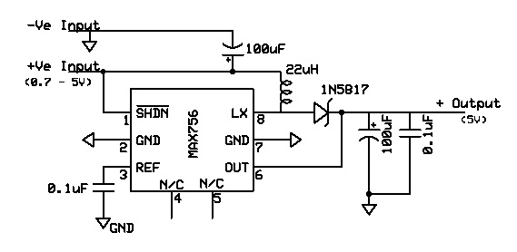
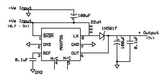
I currently have an application that uses a MAX756 Step-Up Converter to raise voltage from just slightly beow 3.3VDC to 5.0VDC. I would like to be able to control when the MAX756 circuit draws power using one of the Propellers I/O Pins. To oversimplify, I want to be able to go HIGH on a Prop pin and have the MAX756 start converting the 3.3VDC to 5.0VDC.Go LOW on the Prop pin and the MAX756 goes nite-nite. I've attached drawings of the MAX756 circuit, couldn't get the in-line to work--sorry. Between transistors, zener and schottky diodes I'm wiki-outed. What would be an optimal approach? Thanks!!!!! BTW Happy Holidays!

Comments

  • Mike GreenMike Green Posts: 23,101
    edited 2012-12-05 08:02
    You use the shutdown signal (/SHDN). When this is grounded, the Converter turns off. When it goes high (like from a Prop pin), the Converter starts up. Just connect /SHDN to a Prop I/O pin.

    Note the comment on page 5 of the MAX756 datasheet about the /SHDN input. If you connect the MAX756 to a separate power supply from the Propeller so the MAX756 might be disconnected when the Propeller is powered, you should put a resistor (about 1M) in series with /SHDN. This is not necessary if the MAX756 and Propeller are powered from the same source.
  • sunblocksunblock Posts: 55
    edited 2012-12-05 10:22
    Thank you for kind reply :) i am powering them both from the same power source. I am only looking to have the prop control whether the maxim chip draws power. I had considered "splicing" the prop into the shdn pin. But that is where the max756 draws its power and couldnt figure out how to have the chip powered and not have it feed back into prop pin. One thing i dont want is the prop trying to power the max756. Short story, want prop controlling, but not powering. Cant use somthing fancy like a zener diode? :)
  • Mike GreenMike Green Posts: 23,101
    edited 2012-12-05 11:18
    Read the datasheet!

    It explains what each of the pins and signals does. It gives information about the signal levels including how much current /SHDN draws (max. 100nA!)
  • sunblocksunblock Posts: 55
    edited 2012-12-05 15:00
    Mike Green wrote: »
    Read the datasheet!

    Roger, Sir. Will try and rewire my version of the MAX756 circuit to match the datasheet and then hook up the Propeller with the 1MOhm resistor. My mistake. Got to love those digital a$$-kickings.
  • Mike GreenMike Green Posts: 23,101
    edited 2012-12-05 15:11
    I've been accused of "Read the datasheet" obsession before, but there's all sorts of juicy information in them and a lot of questions like yours are answered there, usually better than I could do.
  • sunblocksunblock Posts: 55
    edited 2012-12-05 15:28
    I understand, and as with all almost all other problems I run into in life, I generally do the best I can to research before hitting the help button. But as the SHDN pin is not free in my version of the MAX756 circuit, I'm left with the same dilemma, that being I do not know how to splice in the connection to the Propeller via the 1MOhm resistor--which I have at the ready.
  • Mike GreenMike Green Posts: 23,101
    edited 2012-12-05 15:38
    The /SHDN pin is shown connected to the (+) input supply voltage to the MAX756 because it has to be connected to some positive voltage above 1.5V or the MAX756 will shut down. The easiest way to keep it running is to connect /SHDN to the (+) supply voltage. In your situation, I'd forget the 1M resistor and just connect /SHDN to a Propeller I/O pin and also connect that I/O pin to one end of a 100K resistor and the other end of the resistor to ground. That way, when the Propeller I/O pin is (by default) in input mode, the MAX756 will remain shut down. When your program sets the output register bit for the I/O pin to 1 and the direction register bit for that I/O pin to 1, the MAX756 will start up.
  • sunblocksunblock Posts: 55
    edited 2012-12-05 19:41
    As usual, you are the man. Worked like a champ, and I found a bug in my software to boot. I watched as the SHDN pin voltage dropped deom 3.29V to 0.0-somethingV; and a meter on the output side showed a drop from 5.086VDC to just shy of 2.9VDC.Its not 0VDC, but it is definitely a start in the right direction, which was nowhere a short time ago. Thanks again!
  • Mike GreenMike Green Posts: 23,101
    edited 2012-12-05 19:58
    You probably didn't have a load on the output other than the meter. It will take some time for the output capacitor to discharge completely without a decent load. Try a 220 Ohm resistor.
  • sunblocksunblock Posts: 55
    edited 2012-12-06 10:47
    For the first time in a great while I actually have too much power. So far I have 3 100Ohm resistors in the game on the output side, and I still can't get the at-rest voltage below about 2.7VDC. I guess I need more load, and I won't go into what kind of load I want to dump on it. I'm not real happy about the inductor I'm using either. The Murata 22uH 2.42A fixed inductor is large enough (physically) to brew moonshine in! Think I'm using the wrong product. I looked at the data sheet (yes I did) and the one they suggest (Sumida RCH-654 series) seems to be as rare as a five-legged pig. argh
  • Mike GreenMike Green Posts: 23,101
    edited 2012-12-06 11:07
    Sorry, I had to look at the schematic again ... You're not going to turn off the power to the load using /SHDN. The input voltage is connected to the load via the inductor and Schottky diode which account for the drop from 3.3V to 2.7V. /SHDN shuts off the boost. If you need to shut off the output completely, you'll need a PNP power transistor switch or P-channel MOSFET switch in the output lead
Sign In or Register to comment.