2002 Sumobot Servo question
Back story (Feel free to skip): When I was in Middle school, my local career center had a summer program where one could go and build a sumo bot and compete. I did this and came home with a shiny 3rd place sumobot (We all got to keep our sumobots). Here I am 10 years later with the same sumo bot, some programming knowledge and electrical skilz, minus some pieces! But that's besides the point, I will make do. My plan is to bring this bad boy back to life, minus the SumoBoard and with an Arduino instead.
The issue/question: I have the continuous servos that came with the sumo bot in 2002. I would like to know if they would work the same as the servo on the Learn.Parallax website: http://learn.parallax.com/KickStart/900-00008
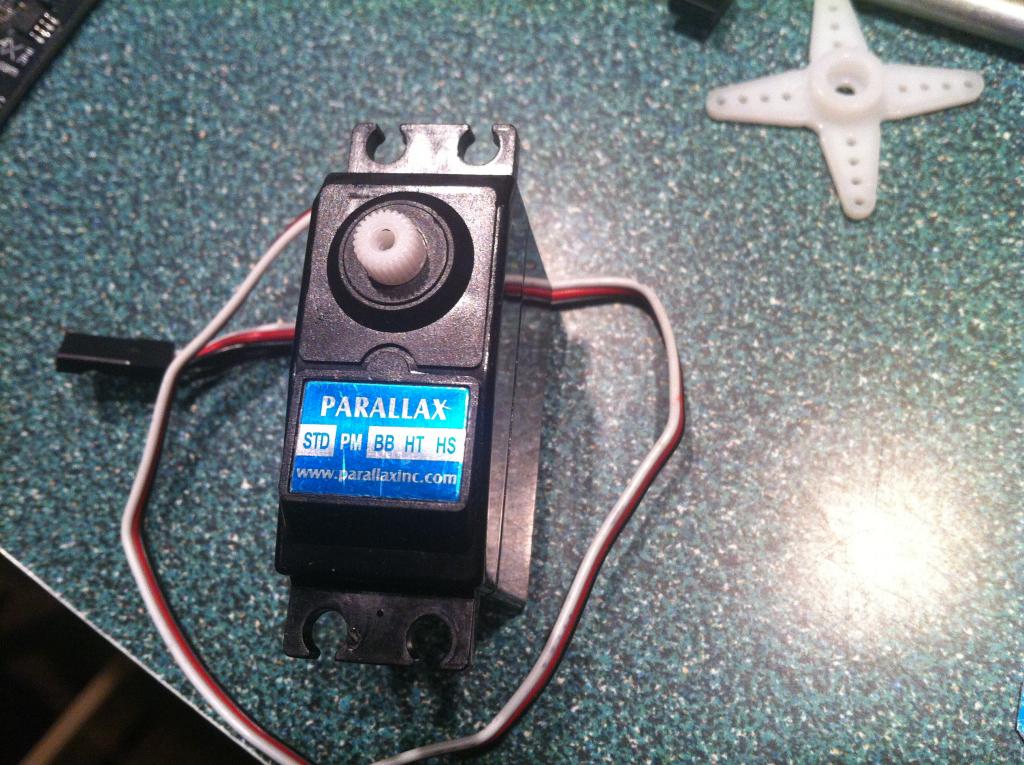
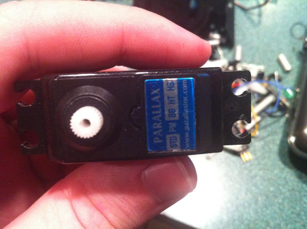
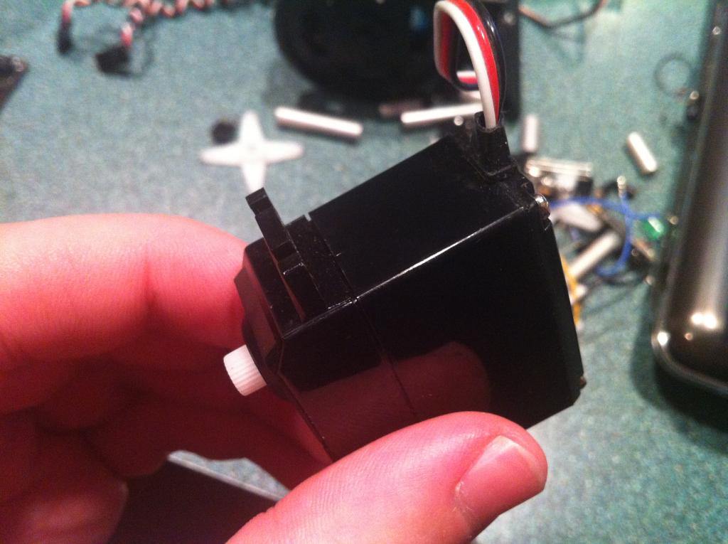
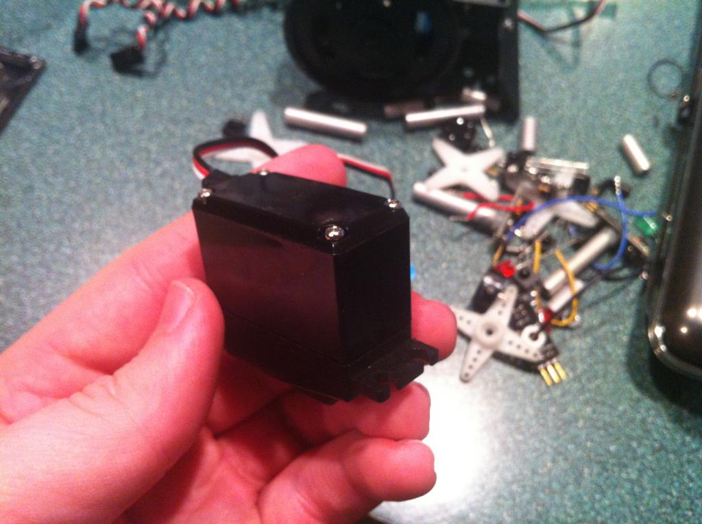
Old servo: There is no adjustment screw by the wires on these servos which is a difference from the one on Learn.Parallax
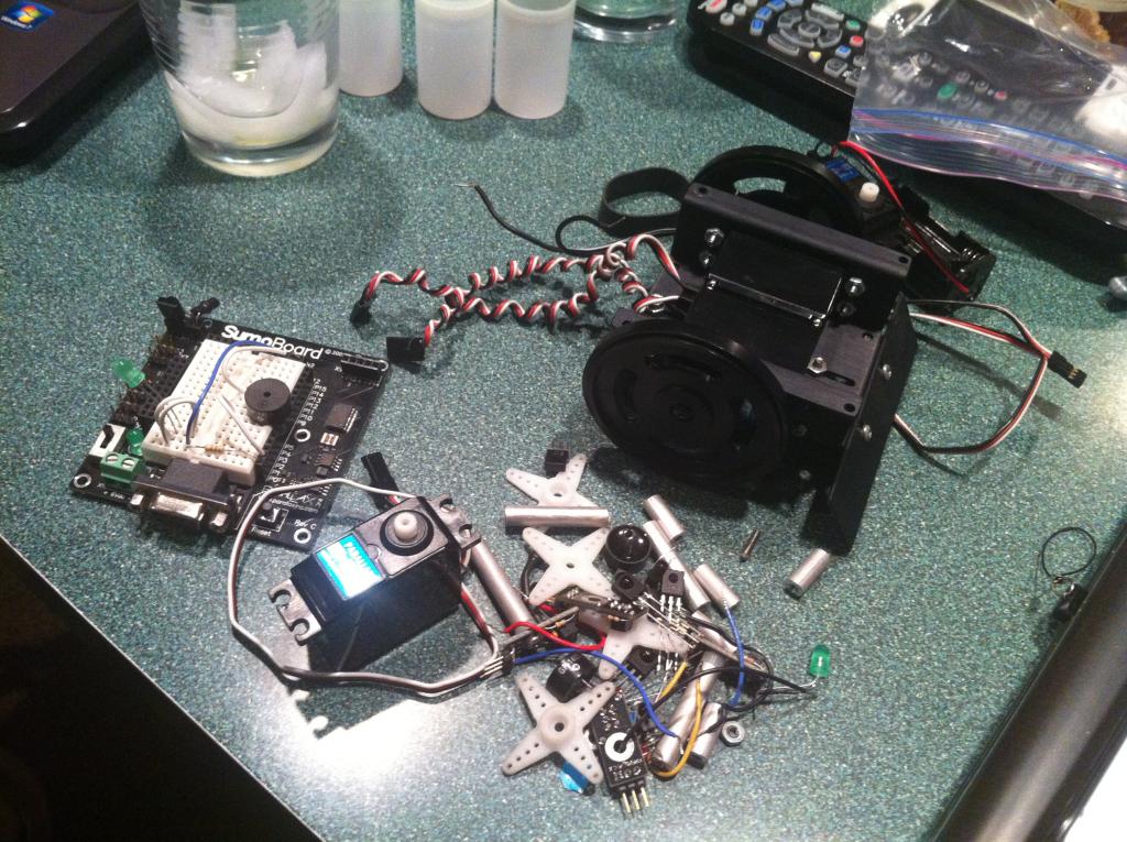
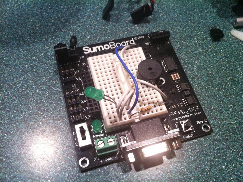
Attached are photos of the old servo along with my sumobot pieces. Also there is a picture of the mainboard if that helps in determining the servos.
I am super excited to start working on this, and robotics in general.
Thank you,
Nathan
The issue/question: I have the continuous servos that came with the sumo bot in 2002. I would like to know if they would work the same as the servo on the Learn.Parallax website: http://learn.parallax.com/KickStart/900-00008
Old servo: There is no adjustment screw by the wires on these servos which is a difference from the one on Learn.Parallax
Attached are photos of the old servo along with my sumobot pieces. Also there is a picture of the mainboard if that helps in determining the servos.


I am super excited to start working on this, and robotics in general.
Thank you,
Nathan


Comments
See the hole in the center of the white spline? I think the adjustment screw might be inside there. I have one batch of CR servos which left the feedback pot in place and you use a jeweler's screwdriver to adjust it.
If it is not there then there is probably no adjustment. Which means you would have to find what pulsewidth works to "center" each servo and use that in your code.
Looking for an adjustment screw down a hole that is supposed to grip the screw that holds the wheel on may damage the screws ability to keep the wheel on.
The ones without any adjustment screw have to be tweaked in software code. It can be done without too much trouble. So I'd probably skip trying to find an adjustment screw at the bottom of an output shaft and do some bench test of what is the sweet spot for each servo in code.
My main question was will it work the same with the PWM but you answered that in your responses. So, even thought they are old servos, if they don't have adjustment screws then I can just calibrate each servo individually.
I just paid off my school loans yesterday and am really excited to get into everything now! I will be sure to post pictures when I accomplish something! It wont be for a little bit because I'm not getting an Arduino till Christmas.