Great Weekend Project For The Propeller DIP Plus Kit
 idbruce
Posts: 6,197
Hello Everyone
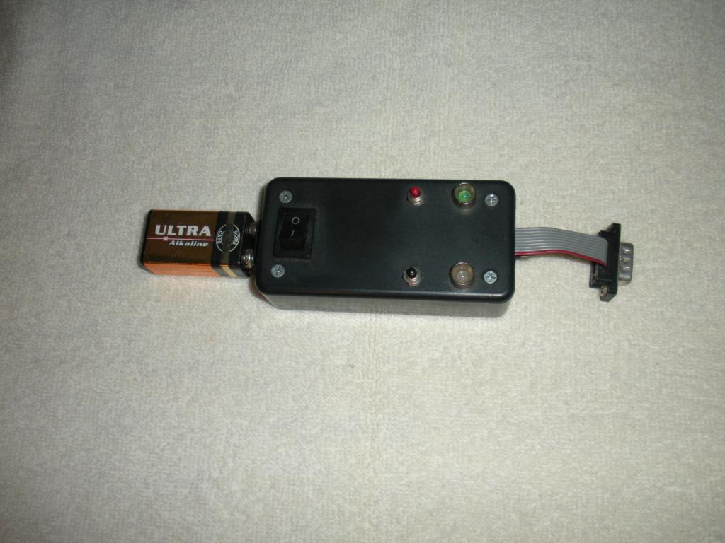
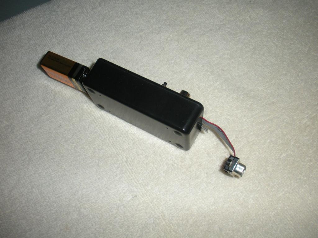
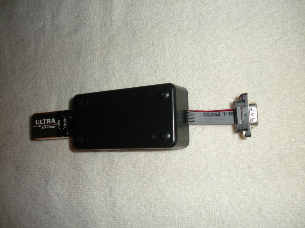
Quite a while back, I built a handheld Propeller chip programmer from the Propeller DIP Plus Kit and this was way before I started getting serious about making my own PCBs. I initially created this tool to program my machinery, but recently I have been using it more and more for programming proto board setups, just so I don't have to drag the computer to the project or the project to the computer. Lately I have been bouncing around the idea of focusing on single sided boards, instead of double sided boards, simply because of the dreaded through holes. So I was wondering just how difficult it would be to make a nice single sided design with the Propeller DIP Plus Kit, so I decided to redesign the original programming tool which was built with jumper wires and perf board, just to see what I could come up with. Additionally, I have also decided to share the design and concept with the forum. Please keep in mind that this project is still on the drawing board and so far it has not been tested, but I believe it is a working design. Please keep in mind that even though it is untested, I do not want this board to be produced and sold commercially, however I am posting it here for individual use, and I will probably share the EAGLE files when I am done.
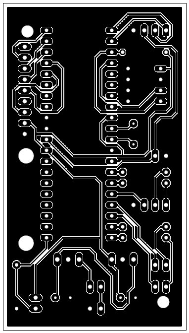
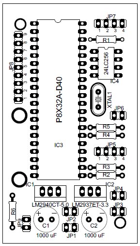
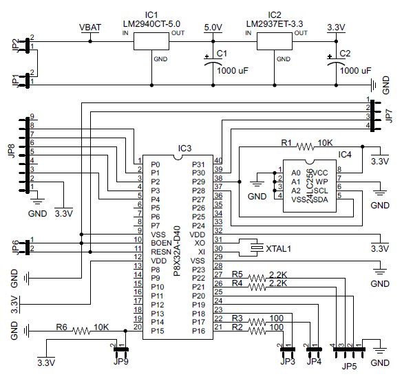
Anyhow, in addition to the Propeller DIP Plus Kit, you will also need several various switches, a project box, a couple LED holders, a couple of bi-color LEDs, several miscellaneous resistors, a row of SIP pins for headers, and you may also need a micro-SD Card Adapter, but this is optional. I probably won't discuss the physical design or programming too much at this point in time, instead I would much rather discuss the electrical design of the programmer, since it is very simple. If you look at the attached images, you will find several photos of the original programmer, an image of the component layout, a photomask image (bottom layer), and a schematic of the design. You may want to print out the component layout, the photomask, and the schematic, just to make it easier to follow along.
The top cover of the project box contains several components which are used for human interaction. These components are intended to be connected to various headers located on the PCB, however these components could also be hardwired direct to the PCB if connectors are not readily available. I will begin my discussion with the various headers, having a component prefix of JP.
JP1 - This header is for the 9V battery clip supplied with the Propeller DIP Plus Kit. Basically it is just the electrical connection from the battery to the PCB.
JP2 - This header is for a rocker switch which provides power from the battery to the entire board. Basically ON and OFF.
JP3 & JP4 - These headers are for two bi-color LEDs. One LED is used for nothing else except to indicate that the board has power. The other LED is used to indicate READY, BUSY, SUCCESS, and FAILURE.
JP5 - This is the connection header going to the Propeller chip that you want to program.
JP6 - This header is used to connect an external pushbutton switch for resetting the Propeller programmer.
JP7 - This header is used for connecting a prop plug to program the internal EEPROM.
JP8 - This header can be used for connecting an optional micro-SD adapter.
JP9 - If an optional micro-SD adapter is utilized, the header will connect to an external slide switch which sets the programming mode. In one position the target chip is programmed from EEPROM and from the other position, it is programmed from the micro-SD. However, if the optional micro-SD adapter is not utilized, then a jumper is placed across these pins to indicate the target should be programmed from EEPROM.
************ LOL.... I just noticed that I missed probably the most important item, the pushbutton and header to start programming the other chip. Oh well, it is late and I am tired. I will probably post more tomorrow when I fix this problem. Until then, glance it over. Should be a nice easy project to gain a new tool for your Parallax projects.
Bruce
EDIT: The new programmer will not include the ribbon cable or the DB9 connector.
EDIT: Please refer to Post #21 for the most recent update.
EDIT: Please refer to Post #23 for the most recent update.


Comments
The capacitors on the regulators are wrong - check the data sheets.
When using the programmer without the optional micro-SD Card Adapter, the files needed for the target are uploaded to the EEPROM of the programmer in the form of data blocks (DAT) using the "file" directive. These files are then downloaded to the target using Chip's PropellerLoader object, which can be found in the OBEX or here, where the object is introduced:
However to directly answer your question, the EEPROM of the programmer is programmed with a computer, in which case, the transfer mode and type will be determined by the input on PIN 15 of the programmer. So basically there will be an IF ELSE situation or CASE, being dependent upon the state of P15.
Bruce
Okay, I know there has been a lot of discussion going on about the use of decoupling capacitors, and I have been paying attention. However when I initially built the first programmer from a Propeller DIP Plus Kit, I wired it according to the schematic presented in PE Kit Lab Fundementals, which does not include the use of decoupling capacitors, and the programmer worked just fine, with the exception of an occasional glitch. So I figured, since board real estate was at a premium for this project, I would attempt the same route. Especially since the PCB and all components must fit into this small box.
To sum it up, the design and schematic utilizes the documentation provided in PE Kit Labs, the parts provided with the Propeller DIP Plus Kit, and is based upon an existing model that has programmed my machinery. Is it a perfect design? I am certain that it isn't. Will it do the job that it is intended to do? I believe that it will, after I shoehorn in the missing components and circuitry for the missing pushbutton. To help facilitate this, I may remove the 5V regulator and one of the capacitors, because it was not used in the first programmer.
Bruce
Bruce
I have decided to try and find a place for decoupling capacitors, but I am going to wait until everything else is figured out.
C.W.
Bruce
Bruce
EDIT: If you want to talk about a tight squeeze, the optional micro-SD Card Adapter will require (2) 3/16 DIA. X 9/16 LNG. standoffs with 4-40 female threads. One standoff is approximately 0.01875" from the C1 decoupling capacitor and the opposing edge of the micro-SD Card Adapter PCB should be approximately 0.020" away from the grounding tab of the regulator. And the 9/16" long standoffs should provide a clearance of approximately of 0.052 - 0.102" between the top of the silicon of the regulator and the bottom of the micro-SD Card Adapter PCB, which is based upon the specifications of the regulator datasheet. It should just "BARELY fit.
Use 100 nF decoupling capacitors.
as far as the rest of the project cool idea if u had alot of machienary like cnc's or somethimg to program. im assuming you came up with this out of need, what do you program with it? nice fit in the enclosure btw
Okay I believe you and agree with you completely, because the datasheet specifically states that, but why would Parallax market a kit with inappropriate capacitors? And I must say that I know these capacitors work for the DIP40 Prop and the 3.3 regulator. I am just wondering why they would do that? I can't understand their reasoning behind this. Perhaps because it is a minimal setup design?????
So you are saying that instead of the 0.01 uF capacitors that I used for the three decoupling capacitors, I should be using 0.1 uF? I was thinking that 0.01 uF was standard. Perhaps I wasn't paying as good attention as I thought I was.
100 nF is the usual value.
You don't need CNC equipment or other machinery to find a use for this project. For example, I have several computers on various tables and the tables are always crowded with datasheets, drawings, books, etc...(always very messy). It is very hard for me to setup electronic experiments near my computers, to say the least, so a portable Propeller programmer is nice to have for this type of situation. With a portable programmer, it shouldn't matter where the target Propeller chip is located, it could be monitoring a sensor located above water at the center of a lake. If the target needs to be reprogrammed, instead of loading your precious laptop into a canoe and paddling out to the target, just grab the handy dandy Portable Prop Programmer. If it drops to the bottom of the lake, of course you will cry, but it will only be a $50 loss instead of $2000.
Yes, I did not have a nice setup for programming my machinery, so I created this gadget to make it easier on me. And as I said before, you can program any Propeller chip that is setup for serial programming.
Well thank you. It was a tight fit on the first one and this new one will propably be just as tight, especially with a micro-SD Card Adapter, however this one will be much neater and appear more professionally designed.
Bruce
More to the point of low current requirements.
Because the Parallax example circuits use very little current, they do not tax the voltage regulators.
The voltage regulator manufactures have to meet their Guaranteed operating performance, therefore they give component values and requirements that will meet their specification.
I like experimenting. The experiment I see here would be to build the circuit and try different size caps to see what I could get away with.
You know? Start with no cap and see what happens. Then add more and more capacitance until the circuit works properly.
Anyhow, I enjoying reading your post. Keep up the good work.
I would be a real *&$%&*, if I did not at least say thank you. So thank you very much for the guidance.
Bruce
Perhaps I should have called it power drain instead of current draw?
I believe I have the design ready and I think I will name this project "PropProgTH", which is the abbreviated version of Propeller Programmer Though Hole or "PropProgSS", which is the abbreviated version of Propeller Programmer Single-Sided.
Since the original post, several capacitors have been added, a couple of capacitors have been changed, and the missing jumper, along with the supporting components have been added. Additionally, the names of the components have all been changed, but most important is the name changes of the jumpers and their intended purpose, so I will now address those name changes to coincide with their intended purpose, which are as follows:
JP2 - This header is used to connect an external pushbutton switch which begins the programming process.
JP10 - This header can be used for connecting an optional micro-SD adapter.
In the attached ZIP file below, you will find several PDFs, which all contain images that pertain to this project. Here is a listing of the contents and the images available:
- PropProgTH_Cmp.pdf - This file contains an image of the component layout.
- PropProgTH_Trc.pdf - This file contains an image of the trace layout (not including polygon fill).
- PropProgTH_TrcCmp.pdf - This file contains an image which combines the trace and component layout.
- PropProgTH_Sch.pdf - This file contains an image of the schematic.
- PropProgTH_Msk.pdf - This file contains an image of the bottom layer of copper or photomask (non-inverted).
Leon, thanks once again for your help with the capacitors.Bruce
Perhaps I am not finished with it just yet. While pondering the project this morning, I came to the conclusion that it is cool project to create a very handy tool for programming Propeller chips, but I also wondered what else could be done with it, especially since I had very little room to work with. After reexamining the circuitry, I came to the conclusion that if I move the circuitry from pin 9 to pin 15, move the circuitry from pin 8 to pin 14, and reroute the ground trace going to R1 and R2 to the bottom of the board, I could gain access to the 5V bus, ground, and 3 additional IO pins, by placing a 5 position right angle header in between the two mounting holes for the micro-SD Card Adapter. By doing so, I could provide a 5 pin header for powering external projects that are setup on a breadboard, which require no more than a maximum of 3 IO pins, 3.3V, and ground. I do believe this would add to the usefulness of this project, and the project will still be a single sided PCB design
How do you like those apples?
Bruce
EDIT: Now that I take a closer look, it now appears that I could install a 6 pin header for 4 IO pins, 3.3V, and ground.
Okay, unless someone finds something wrong with the layout or schematic, this will be the final design
I have added several more items to make it more useful and educational. As I see it, this tool has now become more than just a useful tool to program Propeller chips, it has now evolved into a learning and experimentation device that becomes a useful tool, but it still remains an experimentational device as well. In addition to the previous items, I have now added a 5 pin header for 3 general purpose IO pins, 3.3V, and ground, a 2 pin header for hooking up a standard LED, and a 2 pin header for hooking up a piezo siren. It will be one of those learn as you build projects. I picture the building steps as follows:
- Install all the necessary components to allow it to boot.
- Install all the necessary components for the reset button and a standard pushbutton.
- Install all the necessary components to hook up a standard LED, and experiment with different times and methods of controlling it.
- Install all the necessary components to hook up both bi-color LEDs, and experiment with different times and methods of controlling it, in conjunction with the standard LED.
- Install all the necessary components to hook up the piezo siren, and experiment with different times and methods of controlling it, in conjunction with the standard LED and the two bi-color LEDs.
- Install all the necessary components for the 3 general purpose IO pins and attach them a breadboard, along with 3.3V and ground, and experiment with controlling other various circuitry on the breadboard.
- Install all the necessary components to communicate with another Propeller chip, including, but not limited to, programming it. Experiment with communication and controlling a slave with the project being the master. Then learn how to program another Propeller.
- Install all the necessary components to hook up the micro-SD Card Adapter, and experiment with data logging, file processing, loading file onto another Propeller, etc...
- So on and so forth.................................................
Of course, the Propeller expert need not install all the optional accessories and wiring, however even the Propeller expert may find the optional accessories useful for some purpose or another. Anyhow, after I create and test the prototype, I will probably have several of these boards made by a commercial board house and offer them for sale.Since my last post, several headers have been added, along with the supporting components to add the desired functionality. Additionally, the names of some components have been changed, but most important is the name changes of the jumpers and their intended purpose, so I will now address those name changes to coincide with their intended purpose, which are as follows:
JP2 - This header is for an optional piezo siren.
JP4 - This header is used to connect an external pushbutton switch which begins the programming process.
JP12 - This header can be used for connecting an optional micro-SD adapter.
JP13 - This header can be used to supply a breadboard with 3 IO pins, 3.3V, and grund.
This board is still a single-sided design, so if you are capable of using a photoimaging process to make your own PCBs, then this may be a good project for you, because no plated through holes are required.
In the attached ZIP file below, you will find several PDFs, which all contain images that pertain to this project. Here is a listing of the contents and the images available:
- PropProgTH_Cmp.pdf - This file contains an image of the component layout.
- PropProgTH_Trc.pdf - This file contains an image of the trace layout (not including polygon fill).
- PropProgTH_TrcCmp.pdf - This file contains an image which combines the trace and component layout.
- PropProgTH_Sch.pdf - This file contains an image of the schematic.
- PropProgTH_Msk.pdf - This file contains an image of the bottom layer of copper or photomask (non-inverted).
I hope you like it.Bruce