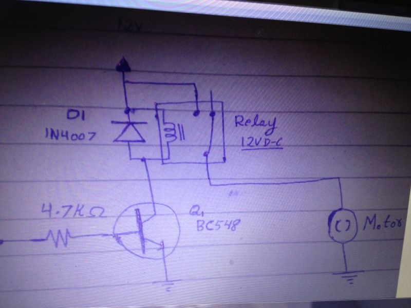
The schematic is correct, but the 4.7K resistor is too high. Try something like 470 Ohms. The 4.7K resistor allows only about 1mA to flow into the transistor's base. Assuming the transistor has 20x-30x current gain, the current to the relay will be only about 20mA-30mA, probably not enough for the relay to close.
Then there is something wrong with how you've wired your device or something wrong with your program.
When the I/O pin is low, the voltage at the I/O pin is too low (< 0.3V) for there to be any current flowing into the transistor's base and the transistor will not conduct (and the relay will be off). When the I/O pin is high, the voltage at the I/O pin will be near 5V and about 10mA will flow through the 470 Ohm resistor into the transistor's base. The BC548 has higher gain than I thought, so there will certainly be enough current to pull in the relay. A bipolar junction transistor normally needs a minimum base voltage of 0.6V for base current to flow.
I can't tell from the photo. You'll have to carefully trace the wires and generate a schematic of how things are actually connected and compare that to what should be there.
Note that the HomeWork Board already has 220 Ohm resistors in all of the I/O pins. That shouldn't make too much of a difference if you have a 470 Ohm resistor in the transistor base lead.
I agree with Mike Green that it is impossible to determine what your circuit is from your photo.
I have a similar problem when attempting to take photos of breadboarded projects.
There are 4 wires that are blocked from view by your red jumper connector.
There is another component, I would assume it's from your transistor, blocked by another red wire.
It looks like from your photo, that your are attempting to control a windscreen wiper motor with some type of Solid State relay
and a transistor.
I can see what you are attempting to do based on your schematic.
Windscreen wiper motors can be quite tricky.
They are designed for a single purpose - clearing water from your windscreen.
Sometimes, As in my case, the Winscreen wiper motor has an internal circuit board controlling how the motor is to function.
The Automotive schematics do not tell you what the internal electronic circuit does.
Have you connected your wiper motor directly to a 12Vdc source to be sure it works without the controller?
I'm no expert, but this is how I would attack this problem.
Set up your homework board to control an LED or lightbulb.
Program the homework board and confirm that your LED it indeed doing what you want it to do.
Once your program is working correctly, connect your motor into the circuit to prove that everything is working.
Pay Very Close Attention to what Mike Green says.
Mike has Never given me any info that is incorrect.
Did you double check that it is a bc548?
If the plastic*TO-92*package is held in front of one's face with the flat side facing toward you and the leads downward, (see picture) the order of the leads, from left to right is*collector, base, emitter.
What happens if you override it with a wire from coll to emit.

 NARX
Posts: 3
NARX
Posts: 3

Comments
When the I/O pin is low, the voltage at the I/O pin is too low (< 0.3V) for there to be any current flowing into the transistor's base and the transistor will not conduct (and the relay will be off). When the I/O pin is high, the voltage at the I/O pin will be near 5V and about 10mA will flow through the 470 Ohm resistor into the transistor's base. The BC548 has higher gain than I thought, so there will certainly be enough current to pull in the relay. A bipolar junction transistor normally needs a minimum base voltage of 0.6V for base current to flow.
Note that the HomeWork Board already has 220 Ohm resistors in all of the I/O pins. That shouldn't make too much of a difference if you have a 470 Ohm resistor in the transistor base lead.
I have a similar problem when attempting to take photos of breadboarded projects.
There are 4 wires that are blocked from view by your red jumper connector.
There is another component, I would assume it's from your transistor, blocked by another red wire.
It looks like from your photo, that your are attempting to control a windscreen wiper motor with some type of Solid State relay
and a transistor.
I can see what you are attempting to do based on your schematic.
Windscreen wiper motors can be quite tricky.
They are designed for a single purpose - clearing water from your windscreen.
Sometimes, As in my case, the Winscreen wiper motor has an internal circuit board controlling how the motor is to function.
The Automotive schematics do not tell you what the internal electronic circuit does.
Have you connected your wiper motor directly to a 12Vdc source to be sure it works without the controller?
I'm no expert, but this is how I would attack this problem.
Set up your homework board to control an LED or lightbulb.
Program the homework board and confirm that your LED it indeed doing what you want it to do.
Once your program is working correctly, connect your motor into the circuit to prove that everything is working.
Pay Very Close Attention to what Mike Green says.
Mike has Never given me any info that is incorrect.
I hope this helps you.
If the plastic*TO-92*package is held in front of one's face with the flat side facing toward you and the leads downward, (see picture) the order of the leads, from left to right is*collector, base, emitter.
What happens if you override it with a wire from coll to emit.