Shop OBEX P1 Docs P2 Docs Learn Events
Photointerupter encoder help! — Parallax Forums

Photointerupter encoder help!

mhamen3mhamen3 Posts: 69
edited 2012-11-13 21:35 in Propeller 1
Hey guys, so I'm trying to make an incremental, single disc, single photointerupter encoder to measure rpm. I've put a photointerupter and a buffer on a bread board and was able to get a +3.3v and 0v output. However, when I hook the circuit up to the actual photointerupter that is mounted to my bot I have problems. I can't seem to get the circuit to switch from high to low consistantly. I should note that the photointerupter is mounted remotely from my circuit through about 18 inches of small gauge wire. Attached is a crude drawing of my circuit, each line with a blue dot on it is a length of 18 inch small gauge wire.

Any help is much appreciated
.
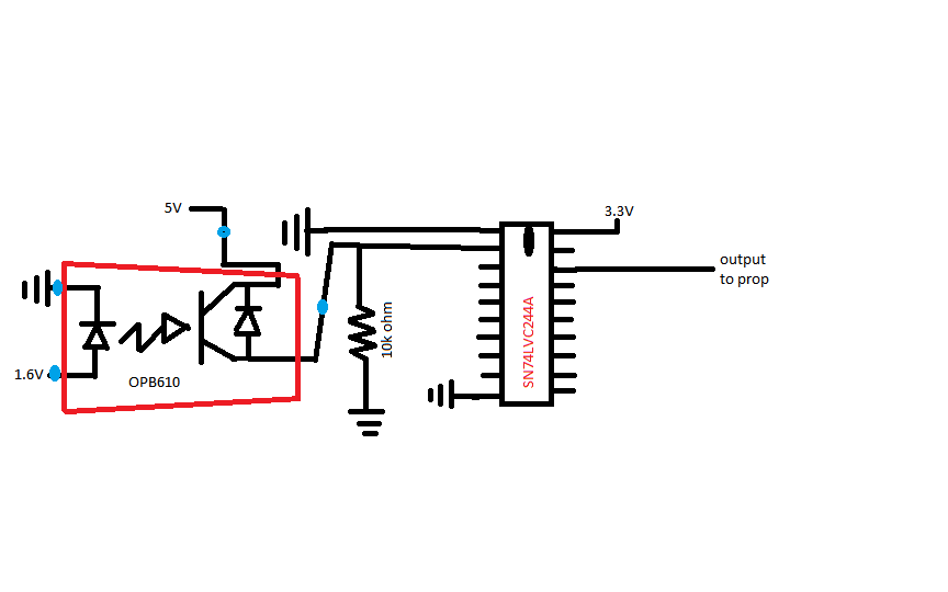
encoder circuit.png
864 x 540 - 16K

Comments

  • Phil Pilgrim (PhiPi)Phil Pilgrim (PhiPi) Posts: 23,514
    edited 2012-11-12 21:31
    I don't know if this is relevant, but can you explain the "1.6V" supply to the IRED. Typically IREDs and LEDs are powered from a higher voltage through a current-limiting resistor. Powering them from a low-impedance fixed voltage could either not be high enough, in which case they would not light, or be too high, which could cause them to fail.

    -Phil
  • mhamen3mhamen3 Posts: 69
    edited 2012-11-12 21:37
    Thanks for the quick reply Phil. The 1.6V is due to the limit of forward current, it is sourced from 5v going through a 100 ohm resistor. The datasheet specifies a max of 1.6V to not supply too much.
    Measurement actually shows about 1.5V going into the LED.
  • Peter JakackiPeter Jakacki Posts: 10,193
    edited 2012-11-12 21:38
    And why the '244? Either you power the collector of the interrupter from 3.3V or else you simply use a current limit resistor in series with the signal to the Prop, try 10K.

    BTW: An LED is a current device, you need a minimum voltage but it is the current that needs to be controlled. Never connect a diode or LED directly to a voltage without current limit or else it will try to draw the maximum current it can to the point of failure. Don't misread the datasheet, understand the device first.
  • Phil Pilgrim (PhiPi)Phil Pilgrim (PhiPi) Posts: 23,514
    edited 2012-11-12 21:46
    mhamen3 wrote:
    The 1.6V is due to the limit of forward current. The datasheet specifies a max of 1.6V to not supply too much.
    Power the IRED from 3.3V or 5V, and use a current-limiting resistor. For example, for a 10 mA current, powered from 5V, use a 330-ohm resistor ( (5V - 1.6V) / 0.010 A). The forward voltage will self-regulate. And Peters' right, you do not need the '244 if you power the phototransistor from 3.3V instead of 5V.

    -Phil
  • mhamen3mhamen3 Posts: 69
    edited 2012-11-12 21:49
    The '244 is used to take advantage of the schmitt trigger built into it to reduce noise.
  • mhamen3mhamen3 Posts: 69
    edited 2012-11-12 21:51
    Thanks Phil. I am powering the LED with 5v going through a 100 ohm resistor to limit current to 50mA (max acceptable). Problems still exist.
  • mhamen3mhamen3 Posts: 69
    edited 2012-11-12 21:53
    My main concern is the fact that the sensor is mounted remotely. Could this cause problems?
  • Peter JakackiPeter Jakacki Posts: 10,193
    edited 2012-11-12 21:54
    Noise from slow edges is very easy to remove in software or even use a feedback resistor from an I/O pin for hysteresis if you are that keen. A lot of this schmitt trigger stuff was done for hard-wired logic whereas a processor can deal with much noisier signals simply in software.

    You may have already damaged the IR LED... try another and don't push the maximum current with 100% duty cycle, 30ma will do.
  • mhamen3mhamen3 Posts: 69
    edited 2012-11-12 21:57
    Thanks, Peter. Could you elaborate on removing noise in software or using a feedback resistor?
  • Peter JakackiPeter Jakacki Posts: 10,193
    edited 2012-11-12 22:08
    Even just the simple delay that the processor has in processing the signal is normally sufficient. It can't resolve or process the noise generated from metastable conditions as the signal passes through the logic threshold.

    Here is a soft+hard solution if you want although I wouldn't bother to do so myself:
    If you use a current limit resistor for the input to the Prop then when your software detects a high or a low it can set another output pin to that same state which when coupled through a resistor (say 100K) back into the sense input will push that input past the sense threshold achieving the desired hysteresis and delivering the equivalent functionality of and external schmitt trigger. A counter can also be set up to do this automatically.

    Anyway, Schmitt triggers also come in single-gate packages such as SOT-23 packs etc.
  • Phil Pilgrim (PhiPi)Phil Pilgrim (PhiPi) Posts: 23,514
    edited 2012-11-12 22:17
    mhamen wrote:
    Thanks Phil. I am powering the LED with 5v going through a 100 ohm resistor to limit current to 50mA (max acceptable).
    That's an Absolute Maximum rating, above which actual damage can occur, not a normal operational value. Limit the current to 10 mA.

    Here's a app note for doing the Schmitt triggering with feedback:

    -Phil
  • mhamen3mhamen3 Posts: 69
    edited 2012-11-12 22:24
    Thanks, Peter. That's helpful. Although I only show 1 photointerupter in my circuit, I'll actually be using 4, and I just had the octobuffer lying around. I don't have enough pins available to do the schmitt trigger equivalent so I may investigate using the counters.
  • Peter JakackiPeter Jakacki Posts: 10,193
    edited 2012-11-12 22:25
    That's an Absolute Maximum rating, above which actual damage can occur, not a normal operational value. Limit the current to 10 mA.

    Here's a app note for doing the Schmitt triggering with feedback:
    -Phil

    I've found that many IR LEDs aren't very efficient so that they need to be driven harder so 30ma max but anywhere from 10ma upwards as Phil mentioned. BTW, the resistor is calculated by subtracting the voltage drop of the IR LED (around 1.2V) from the supply voltage. So 100 ohms delivers around 38ma, not 50ma.

    @Phil: thanks for the link, didn't know there was one.

    EDIT: skip the schmitt triggers/hysteresis, I have never needed them
  • mhamen3mhamen3 Posts: 69
    edited 2012-11-12 22:26
    Awesome, Phil. I'll check that out. I really appreciate your help, guys.
  • Phil Pilgrim (PhiPi)Phil Pilgrim (PhiPi) Posts: 23,514
    edited 2012-11-12 22:32
    mhamen3,

    What is the anticipated frequency of your output pulses when run from your bot? Have you tried turning the shaft slowly by hand to see if that makes a difference?

    -Phil
  • mhamen3mhamen3 Posts: 69
    edited 2012-11-12 22:58
    I tried turning the disc to get a change but it was very finicky as to when it would turn the output low. As I mentioned, on a breadboard it worked fine, but when I connected the sensor through longer wires it didn't work well. I'm expecting 500 pulses/sec as a maximum.
  • Phil Pilgrim (PhiPi)Phil Pilgrim (PhiPi) Posts: 23,514
    edited 2012-11-12 23:37
    What are you using for an encoder disc?

    -Phil
  • jmgjmg Posts: 15,183
    edited 2012-11-13 01:18
    mhamen3 wrote: »
    I tried turning the disc to get a change but it was very finicky as to when it would turn the output low. As I mentioned, on a breadboard it worked fine, but when I connected the sensor through longer wires it didn't work well. I'm expecting 500 pulses/sec as a maximum.

    You show a pull-up design, so if it is hard/rare to see a low, that suggests stray light may be a problem, or your disc.is not opaque enough
    Try different orientations, and disc offsets

    The OPB610 specs say operating at 5mA If, it will give at least 1mA Ic ( ie a CTR of > 20% )
    With 10k load and 3v3 supply, you will be ~ 170uA threshold, and 100 ohms drives at ~ 34mA.
    I'd drop the drive current to 5mA and check again and increase the drive (and drop the load resistor at the same time) only if you need to overcome external light. (eg you could consider 20mA drive, and 560 - 1k load, if external light is an issue )
  • mhamen3mhamen3 Posts: 69
    edited 2012-11-13 10:24
    Phil, I'm using 1.6mm thick black g10 for a disc. I'm not too concerned with it's opacity. Although the slot width could, or lack thereof, be an issue. I'll machine a disc with wider fins and try it out if jmg's tips don't help.

    JMG, I really appreciate your response. I'll try your tips when I get home tonight. Just for clarity, are you refering the 10kohm resistor in my circuit as the load resistor?
  • tonyp12tonyp12 Posts: 1,951
    edited 2012-11-13 11:00
    Pull-up the Prop input with a 10K resistor,
    when light reaches the transistor it will connect the trace to GND and you should see a 0 on input pin.

    The Prop switch hard at 1/2 Vcc, so try 20k to 100k Ohm pull-up if the 10K is to strong of a pull-up.
    attachment.php?attachmentid=96959&d=1352832958
    421 x 210 - 10K
  • Alex.StanfieldAlex.Stanfield Posts: 198
    edited 2012-11-13 11:30
    Does it have to be optic?

    I'll prefer a magnetic sensor, with at least two options depending on the mechanics involved.

    1) Fix a small rare earth magnet to the shaft and use a hall effect switch (not sensor but a switch like Allegro's A110x family)

    2) Use a cam sensor (like Melexis' MLX90217) with the small magnet glued to the sensor and place it near a part of the motor/system that rotates (must be a magnetic metal part). This one is even suited for automotive use.

    Alex
  • mhamen3mhamen3 Posts: 69
    edited 2012-11-13 11:54
    Thanks, Alex. These aren't bad ideas I just don't think I'll get the resolution I need for my application with these options. Space constrictions on my bot made it neccessary to mount the encoders downstream of the gearbox and directly on the axle. I'm shooting for 24 rises/falls per shaft revolution and I fear hall effect switches would severely limit this.
  • Alex.StanfieldAlex.Stanfield Posts: 198
    edited 2012-11-13 12:22
    mhamen3 wrote: »
    Thanks, Alex. These aren't bad ideas I just don't think I'll get the resolution I need for my application with these options. Space constrictions on my bot made it neccessary to mount the encoders downstream of the gearbox and directly on the axle. I'm shooting for 24 rises/falls per shaft revolution and I fear hall effect switches would severely limit this.

    Take a look at the datasheet for MLX90217, it's self-adjusting and 15°/tooth doesn't seem a big challenge for that chip, unless the disc is really small.
    If you are set to build a disc and you can make it metallic, I'll give it a try. It all depends on your disc's design (to force a +/- 5mT flux variation on the sensor).

    Just one more idea, if you can get any metallic protuberance upstream to the driving motor (or place a magnet there, like a small square one on the motor's shaft) and depending on your gear ratio maybe you can just have 1 pulse per motor revolution and it could be enough, only you know.

    Alex
  • mhamen3mhamen3 Posts: 69
    edited 2012-11-13 15:32
    Thanks again, Alex. The MLX90217 looks seriously promising. If i exhaust all the advice in the forum and can't get it to work then I will probably look into these. If not, this will definitely be something I'll keep in mind for future use.

  • mhamen3mhamen3 Posts: 69
    edited 2012-11-13 16:48
    I've got it working. Changing the resistor to 1kohm solved the problem. THANKS A LOT TO ALL WHO OFFERED HELP!!
  • mhamen3mhamen3 Posts: 69
    edited 2012-11-13 21:35
    Thanks, guys. Figured I'd attach a pic of the bot for reference; and to show what the prop can be used for. I am very grateful for all the help here.

    The bot is scratch built using resin casting. All molds were produced in my 14 sq ft closet.

    20121108_201428_HDR (1).jpg


    my flickr documents the process a little better. Or check out my thread on the lynxmotion forum.
    http://www.flickr.com/photos/marcbots/sets/72157631912836115/
    http://lynxmotion.net/viewtopic.php?f=8&t=7256
    1024 x 768 - 104K
Sign In or Register to comment.