

GearMotor/Wheel and Quadrature Encoder set up for < 6 dollars a wheel
 rwgast_logicdesign
Posts: 1,464
rwgast_logicdesign
Posts: 1,464
Ok so when I started building my robot I looked in to many different options for a drive train and quadrature encoders. There seemed to be plenty of kits out there with wheel encoders/wheels/gear motors but they all seemed a little pricey especially since I wanted to build an all wheel drive 4 to 6 wheeler originally. Anyways Ive come up with a solution and decided to show everyone how I did it maybe someone else will follow my write up or at least get inspired. Now Ive got to say this is a very cheap way to get a drive train, but it will require you have tools, epoxys, and other materials! This project is all done using hand tools, no fancy cnc or lathe required.
Heres the biggest catch, this project is cheap becuase the materials im using are surplus blow out. Now you can get these motors for about 12 dollars regularly but right now there only 2.95!! The wheels im using arent the greatest either but at 25 cents a pop, theyll do for a while.
So lets take a look at the final assembly, before going any further,
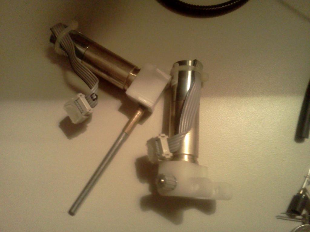
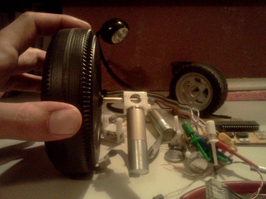
So the left picture is the original motor, and then the motor with a moded output shaft. The picture on the right is the full assembly! The technique im using in this tutorial can be adapted to most any motor and axel wheel set up.
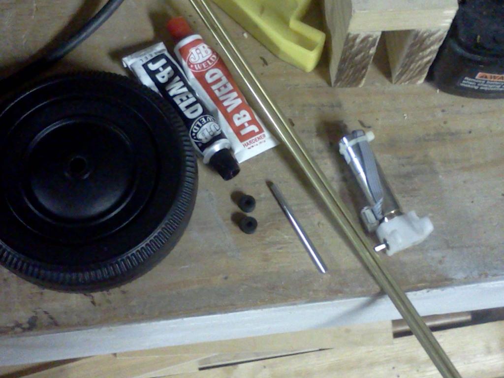
Materials & Tools


So lets round up what we need, here is a list and some tips for sourcing more uncommon materials I used
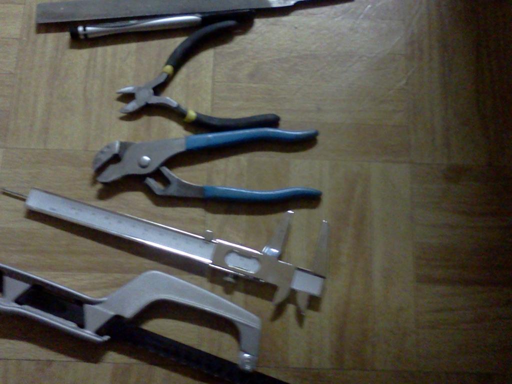
Tools:
Channel locks
Hammer
Soldering iron
Metal File
Mini dykes
Caliper
Hack Saw
Sharpee
Materials:
Faulhaber 141:1 motor
CheapO Wheels
JB Weld
Wet Dry sand papers
Erector Set Axel or 4mm solid rod
Eector set rubber Grommets
3mm ID brass tube
4mm ID brass tube
flux
First you will need the awesome motors. These motors are pretty strong for there size and will power a small bot easily. I haven't gotten a full weight test done but im sure they will push 5 to 10lbs easily, and are small enough to build a micro mouse/sumo style bot around. They also have built in quadrature encoders using hall sensors.
141:1 Gear motor 80RPM@6V with quadrature encoder for 2.95 So these motors are a blowout due to the wire being nicked, the cuts are so small they dont matter and a bit of rubber cement would insulate them well if you have the motivation to even bother with it!
SAME MOTOR @ 11.95 right now there on sale for 7.95 actually. Im posting this link in case your reading this write up after the blowout 2.95 specials are gone
Robot Room has a pretty detailed write up on this motor, including voltage and enocder details. One thing is he says he had problems at 12v with his motors. Electronics goldmine says these guys will do 3-18vdc, I havent tested them at 18v but I can say none of the 6 motor I bought have any issue at 12v.
Next you need to pic some cheap wheels both sets are 4 wheels for a dollar and have 8mm hub holes,
4 & 3/14 by 1 & 1/2 inch hollow plastic
6 by 1 & 5/8 inch hollow plastic
Uncommon materials used
So the silver axle is a piece from an erector set, but its just a 4mm by 6cm rod. You can find 4mm steel rod all over, I noticed that those cheap tent stake that look like a rod in an L shape are 4mm. Also typing 4mm rod in ebay gave me some good results for cheap, or if you want erector axles because your exactly duplicating me try this. The two black rubber grommets are also common in erector sets, they are 9mm outer diameter with 4mm center hole, your probably going to have to get creative if you don't have erector sets, im sure super glue and 4mm ID hose would also work well. Like I said 4mm is common in the RC world so buying nice RC wheels will eliminate the need for the rubber grommets, as there only to press the cheap wheels to the axle.
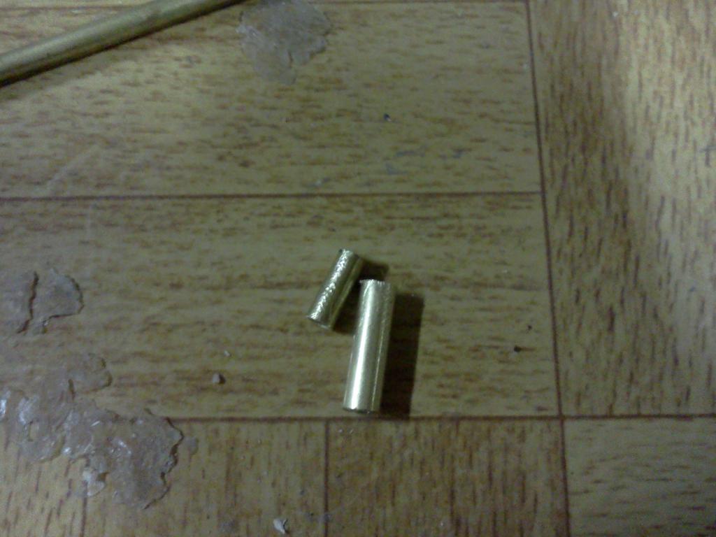
The next thing you will need you probably dont have laying around is two lengths of brass tube, I got these at my local hobby RC shop. The first rod needs to have a 3mm inner diameter and the second needs a 4mm inner diameter. These rods are going to act as a shaft coupler, when we build the axel. Basically the faulhaber/micromo motors have a 3mm output shaft, I figured if im going to extend the gear motor output shaft I should kick it up to 4mm. My reasoning for moving to 4mm is not only because of the rubber grommets I used to press the wheels but also 4mm hub holes are super common at the RC shop this gives me a wide range of good tires to choose from later. The tires for model planes got up to 6 inched with a 4mm hub hole. So heres the issue im not sure exactly where to buy these tubes online a little searching shows that they might actually be standard and nt metric which is probably why the tube didn't fit tight on the 3mm shaft. If it helps I used "K&S precision metals" brass tubes bar codes end in 11146 and 11147, amazon has an assortment of k&s tube pieces for 3.09. Any brass tubes with the right inner diameters should do though, if anyone finds a good source for tubes and they fit tight on the motor shaft let me know.
Lets Build it Already!!
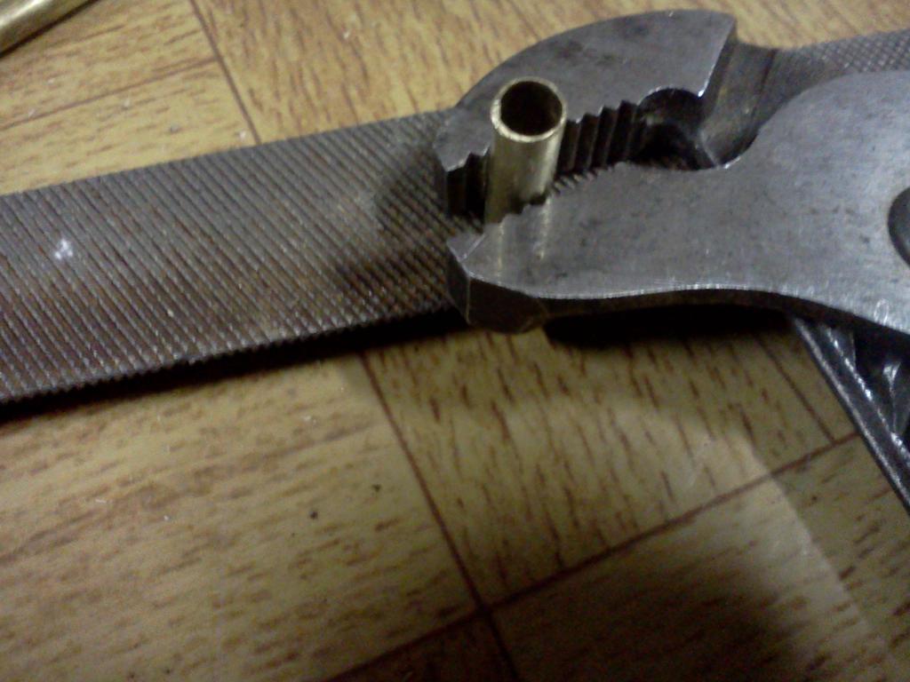
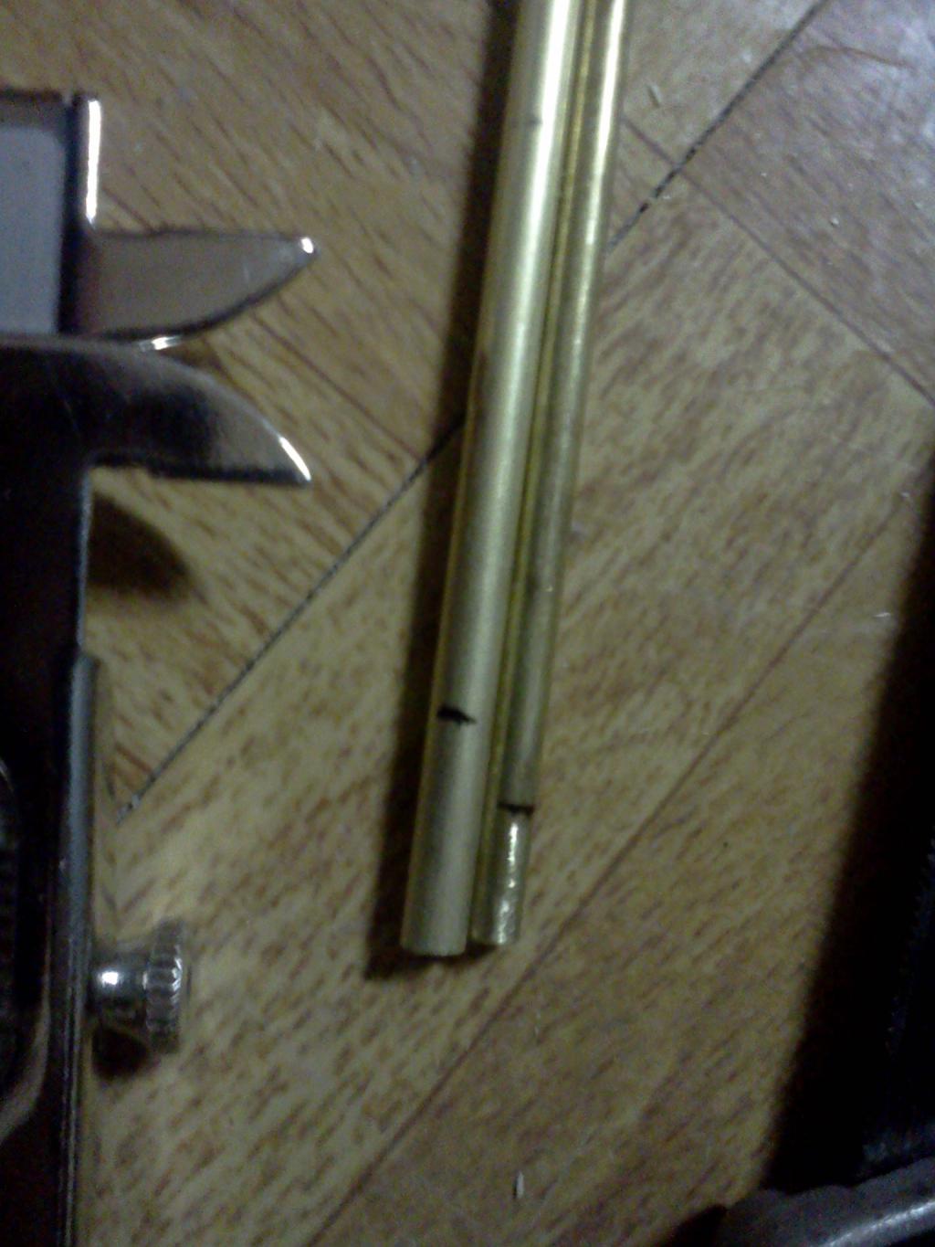
The first thing your going to do is measure your cut marks for the brass tubes. Your going to need a piece of 3mm ID tube cut to 8mm long, then a piece of the 4mm ID tube cut to 16mm long. The thing is when you cut your tubes its never a nice clean cut so you going to want to make your measuring marks at 9mm and 17mm respectively, this will give you an extra mm to work with you clean your cuts with a file and ream the tubes.


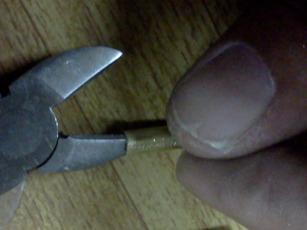
Now you want to go ahead and clean your tubes up, I always starts by gripping them with channel locks and rubbing them on a file. The thing is you want your tubes to be groud down a straight as possible. So after the tube is ground down clean, I then put the file flat on the table and push the tube across it with my hands one way until its realitvely flat (look up lapping a heat sink for how to flatten a surface by hand). After the tube is cleanly filed and decently flat, I ream the tube with small dykes, this is just twisting a blade on the inside of the tube to debbur it.

Heres the biggest catch, this project is cheap becuase the materials im using are surplus blow out. Now you can get these motors for about 12 dollars regularly but right now there only 2.95!! The wheels im using arent the greatest either but at 25 cents a pop, theyll do for a while.
So lets take a look at the final assembly, before going any further,
So the left picture is the original motor, and then the motor with a moded output shaft. The picture on the right is the full assembly! The technique im using in this tutorial can be adapted to most any motor and axel wheel set up.
Materials & Tools
So lets round up what we need, here is a list and some tips for sourcing more uncommon materials I used
Tools:
Channel locks
Hammer
Soldering iron
Metal File
Mini dykes
Caliper
Hack Saw
Sharpee
Materials:
Faulhaber 141:1 motor
CheapO Wheels
JB Weld
Wet Dry sand papers
Erector Set Axel or 4mm solid rod
Eector set rubber Grommets
3mm ID brass tube
4mm ID brass tube
flux
First you will need the awesome motors. These motors are pretty strong for there size and will power a small bot easily. I haven't gotten a full weight test done but im sure they will push 5 to 10lbs easily, and are small enough to build a micro mouse/sumo style bot around. They also have built in quadrature encoders using hall sensors.
141:1 Gear motor 80RPM@6V with quadrature encoder for 2.95 So these motors are a blowout due to the wire being nicked, the cuts are so small they dont matter and a bit of rubber cement would insulate them well if you have the motivation to even bother with it!
SAME MOTOR @ 11.95 right now there on sale for 7.95 actually. Im posting this link in case your reading this write up after the blowout 2.95 specials are gone
Robot Room has a pretty detailed write up on this motor, including voltage and enocder details. One thing is he says he had problems at 12v with his motors. Electronics goldmine says these guys will do 3-18vdc, I havent tested them at 18v but I can say none of the 6 motor I bought have any issue at 12v.
Next you need to pic some cheap wheels both sets are 4 wheels for a dollar and have 8mm hub holes,
4 & 3/14 by 1 & 1/2 inch hollow plastic
6 by 1 & 5/8 inch hollow plastic
Uncommon materials used
So the silver axle is a piece from an erector set, but its just a 4mm by 6cm rod. You can find 4mm steel rod all over, I noticed that those cheap tent stake that look like a rod in an L shape are 4mm. Also typing 4mm rod in ebay gave me some good results for cheap, or if you want erector axles because your exactly duplicating me try this. The two black rubber grommets are also common in erector sets, they are 9mm outer diameter with 4mm center hole, your probably going to have to get creative if you don't have erector sets, im sure super glue and 4mm ID hose would also work well. Like I said 4mm is common in the RC world so buying nice RC wheels will eliminate the need for the rubber grommets, as there only to press the cheap wheels to the axle.
The next thing you will need you probably dont have laying around is two lengths of brass tube, I got these at my local hobby RC shop. The first rod needs to have a 3mm inner diameter and the second needs a 4mm inner diameter. These rods are going to act as a shaft coupler, when we build the axel. Basically the faulhaber/micromo motors have a 3mm output shaft, I figured if im going to extend the gear motor output shaft I should kick it up to 4mm. My reasoning for moving to 4mm is not only because of the rubber grommets I used to press the wheels but also 4mm hub holes are super common at the RC shop this gives me a wide range of good tires to choose from later. The tires for model planes got up to 6 inched with a 4mm hub hole. So heres the issue im not sure exactly where to buy these tubes online a little searching shows that they might actually be standard and nt metric which is probably why the tube didn't fit tight on the 3mm shaft. If it helps I used "K&S precision metals" brass tubes bar codes end in 11146 and 11147, amazon has an assortment of k&s tube pieces for 3.09. Any brass tubes with the right inner diameters should do though, if anyone finds a good source for tubes and they fit tight on the motor shaft let me know.
Lets Build it Already!!
The first thing your going to do is measure your cut marks for the brass tubes. Your going to need a piece of 3mm ID tube cut to 8mm long, then a piece of the 4mm ID tube cut to 16mm long. The thing is when you cut your tubes its never a nice clean cut so you going to want to make your measuring marks at 9mm and 17mm respectively, this will give you an extra mm to work with you clean your cuts with a file and ream the tubes.
Now you want to go ahead and clean your tubes up, I always starts by gripping them with channel locks and rubbing them on a file. The thing is you want your tubes to be groud down a straight as possible. So after the tube is ground down clean, I then put the file flat on the table and push the tube across it with my hands one way until its realitvely flat (look up lapping a heat sink for how to flatten a surface by hand). After the tube is cleanly filed and decently flat, I ream the tube with small dykes, this is just twisting a blade on the inside of the tube to debbur it.

1024 x 768 - 76K

1024 x 768 - 59K
1024 x 768 - 76K
1024 x 768 - 84K
1024 x 768 - 73K
1024 x 1365 - 121K

1024 x 768 - 62K
1024 x 768 - 62K

1024 x 768 - 83K
Comments
After the axle has been pressed put some flux around the inner wall of the 4mm tube and the outer walls of the 3mm tube. then press the 3mm tube in to the 4mm, just use your fingers no need for a hammer, on this one! When the 3mm tube is insterted, if you did all your cuts and filing right you should see about 1mm, of the 3mm tube, protruding from the end of the 4mm tube. When measured with a caliper the total length of the brass tubes should be 17mm. The reason we have 1mm of the smaller tube hanging out is because that's where were going to apply the solder.
To solder the two tubes I use a 40 watt iron with a big chisel tip shown above, im not sure if a lower wattage iron would work but if not a butane touch or jb weld will also work. Since you pre fluxed the tubes it should be relatively easy to soldier the tubes. First I hold the axle with the channel locks and use the iron to heat around the seam of the tubes for a minute or so. Next i melt my soldier on to the tip of the iron and then tab it around the seam where the tubes meet. I know this is how you get cold joints but trust me, basically were just getting the tubes hot and getting solder to stick to them.
After I've done what looks like a decent solder job around the seem, i switch to a smaller iron tip and then reheat the solder, this gauntness i don't have a cold joint and also the smaller tip really allows me to make the solder job look alot cleaner. After the soldier is cooled I file away any excess and make sure to re ream the inside of the 3mm tube. After a good filing and reaming I use 600 the 1000 grit wet dry to make things look nice
Ok so now is the biggest pain in the butt, mounting the axle to the motor. First you need to remove the pinion that comes with the motor. If you dont have a .9mm hex key to remove faulhabers gears, you can usually take the smallest flat head in a precision set and stick it in between the nylon gearbox and the pinion, then kind of just walk the pinion gear up the shaft by pushing up on the screw driver a little then moving it to the other side of the gear and pushing up a little, over an over again. Once the gear is off you want to mix up some JB Weld and lt it sit for 5 minutes or so till it start to get a bit thicker. Apply a little built of weld inside the 3mm tubing and then on the flat part of the axle. Make sure you dont have globs of jb weld coming out the axel when you slide it down the shaft. You don't want to get epoxy in the motors gear box just make sure your really clean with the JB weld. So if you are using the same tubes I did you'll notice that the axle doesn't slide on to the shaft tight. It is important to make sure that the axle is as straight as possible while the JB weld is setting. I usually turn the motor on at 3v which makes it spin super slow, next I lightly touch the end of the axle with my index finger. If i notice the shaft isnt spinning straight i move it with my finger until its as straight as I can possibly get it. Usually I let the motor spin and keep the axle straight with my finger for about 30 minutes, then i set the motor down shaft pointing to the ceiling. I then turn the motor back on every 5 to 10 minutes and make sure its still straight, i do this until i feel reasonably comfortable the jb weld has set enough that the shaft is going to stay exactly how I set it with my finger.
So thats it, that alll there is to it