

Lemonade from lemons bot
 rwgast_logicdesign
Posts: 1,464
rwgast_logicdesign
Posts: 1,464
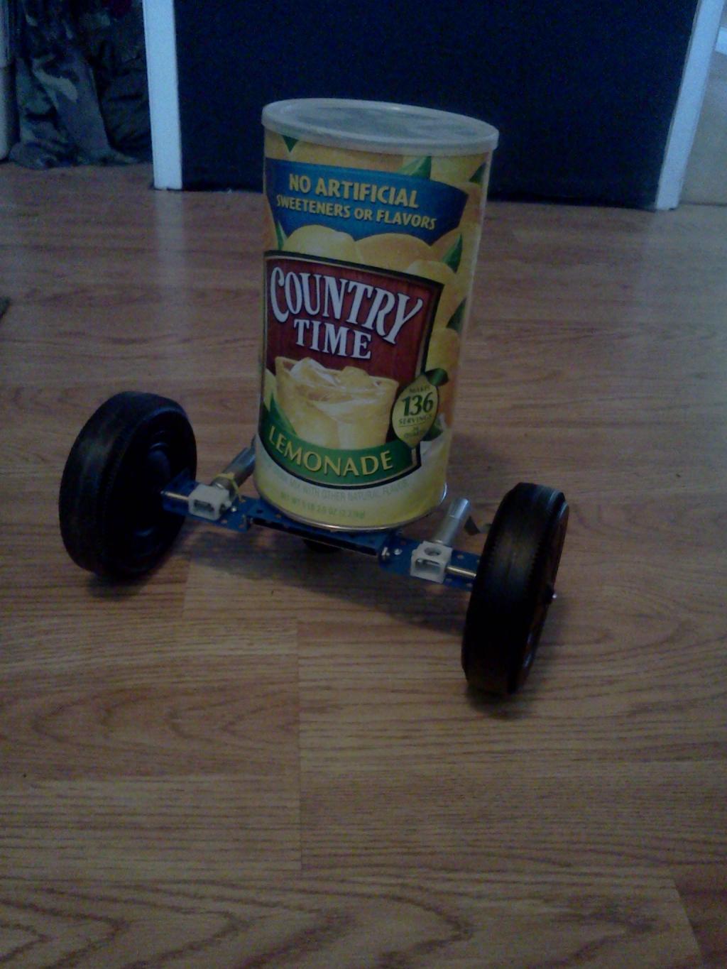
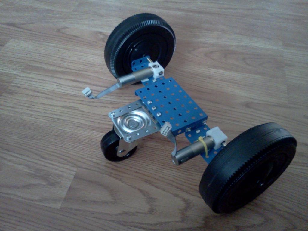
So out of a lack of patients and wanting to get a rolling platform done like now! Ive decided to hold off on a 4WD robot and build a 3 wheeler for in the house, The platform is almost done needs a little reinforcement and then, the base shall be complete next comes the batterys and H-Bridge. Anyways this thing is made from a shoe string budget, luckily I have alot of erector stuff laying around. Total cost so far about 12 dollars for motors, and brass tubing to fit new axels. Oh ya and a buck for the wheels, everything else is just stuff I had! So here is where im headed


1024 x 1365 - 131K
1024 x 768 - 80K
Comments
Looks like a good start.
For small bots, simple H-bridges from relays work well...
http://forums.parallax.com/showthread.php?106382-4-State-Relay-H-Bridge
as far as an hbridge i have 3 or 4 different chips around, i think an stm l293E will be what i use as its 1 to 2 amps and these motors stall just over an amp at 12v, but i need to test the 18v electronics goldmine said these motors would do before making a final desicision.
im not sure if this is a good idea but im thinking about runing a boost converter so my hbridge is always at max voltage no matter how low the batterys get i can be pumping 12 or 18v to the hbridge. i know one of the polulu bots has some way of providing a 9v constant to the motors
Thanks for taking time to show it to us.
Also thanks for the heads up about the good deal on these motors. Mine arrived Friday and they show look, sound and feel nice (they also smell nice, but I'm still ignorant about how they taste).
well unfourtanetly the 3mm tube isnt flush around the motor shaft due to the d shape, so i have to baby sit the axels while they the jb weld drys, i ended up ruining one last night becuase i pressed in a warped axel and it caused it to set crooked even though i held it straight for an hour, so now im out a motor becuase idk how to remove jb weld, o well ill just order another at 3 bucks. I ordered six so i could make a 2wd and 4wd.
A very sharp Exacto knife set will cut JB Weld.
As fars as getting the axels off im just gonna have to wait for the .9mm hex so I can take apart the gear box and put the the axel in the oven, I cant get inside the axel with a knife of file. JB welds site says itll break down at 600f my iron wont get it that hot though so ill use the oven
Edit: Not the wires but the plastic wire casings.
Ok thats a link to a write up on the axels
Don't put it in your home oven. The JB Weld is likely to give off some nasty vapors. Also 600F is "self clean" temperatures for an oven and could be hard on the oven (if it can get that hot). It's likely to do more damage to the oven than the motor cost you.
I'd think some sort of blow torch would be a better choice for heating the JB Weld.
unfourtantely i dont have a scale i just set a box of motors on the platform which was pretty heavy compared to a 10lb dumbel.
these motors are definately decent, at 12v i was goin as fast as a cheap rc car with no load on top
I have had problems with keeping the wheels on and straight. I ordered fitted hubs from fingertech($1), and then mounted some hollow wheels($.25) from Goldmine?. The problem that I encountered is that the various torques on the wheels cause the 3 set screws in the hub and in the gears to tear through the metal connecting rods. This causes the gears to free-wheel and the wheel to go kittywampus. The screws also damage themselves and then become slightly impossible to remove.
I used polymorph to hold the motors to an acrylic base... it is reusable, but a pain to remove:) I have ten more motors... so hacking away is my present approach.
My plan is to remove all the gears and try again using your general approach:)
In experiments, I have been using Ray's Merlin dual dc motor driver... http://rayslogic.com/Propeller/Products/Merlin/Merlin.htmexcellent, but for simplicity, connectivity and mounting I am thinking of going to the same chip on a breakout board from Sparkfun.
Rich
as far as a motor driver the stm l293e is what im using it does 1 amp continously maxes at 1.5. under load these motors run at 800ma @ 18v, but they stall at 1.65 amps which is just outa the chips rating.. so my plan is just to watch monitor the current of the motor and never allow it more than 1.3 amps or so. if your using these motors at 12v stall is at 1a so theres no need for current feedback, im assuming most will run these in the 6 to 9v range. the l293e is very easy to use very few connections, and can be sampled from stm. the stm l293b version is the same as the e except its an 18 pin dip, the e is a 20pin which has voltage monitoring that i intend to use with a boost regulator to compensate for battery drain as needed. in either case if you use my setup an stm l293e/b is easy and free and well in the realm of handeling these motors there so efficent! just dont hook up over 5v on the encoder power instead of the motor power
The next best thing to plywood for building robots.
https://www.sparkfun.com/products/10950
Gareth has some cool Polymorph (aka Shape Lock) tutorials on Let's Make Robots.
I recently used Polymorph to make landing gear for my hexacopter (the white "7" shaped things under each motor).
Thanks, I think they look nice too. Yes, I used a mold. I used 1/4" plywood with the shape I wanted cut out from the wood. I used three pieces of plywood. One was just a square base and the other two joined together to make the mold. I bolted the two mold pieces to the base piece to hold them in place. I used copper tape to cover the wood wherever the Polymorph would come in contact with it (Al tape would have been less expensive, but I had Cu tape on hand). I then heated the Polymorph up (I used a heat gun so things wouldn't get wet) and squished the Polymorph into the mold. I preweighed the Polymorph so each landing gear would weigh the same.
Each one used 8.8g of Polymorph. All six used about 53g of Polymorph.
One of the nice features of Polymorph is it can be reused. After I had made the landing gear and I tried to figure out how to attach them to the hexacopter, I realized it would have been better to have had nuts embedded in the plastic so I made a few changes to the mold and cut off the tops of my landing gear and remelted and remolded them. It didn't take long to add the nuts this way. The bolts that held the nuts in postion within the mold also made nice holes when they were removed which made mounting the landing gear easy.
Looks great, Duane! +2 for you and the olding tips!
Thanks Rick and rwgast, I'm pleased with how they turned out. My first attempt (I only made one) was too thin and flexed too much. These have a nice spring to them but don't have a problem holding the hexacopter up.
This stuff is very strong. It's flexible (similar to Sugru) and tough. I'll try to make a video of flexing some of it and showing how strong it is tomorrow.
I did make the video yesterday, but I didn't post it to the forum until today. It's great stuff.
my intententions are to cram motor and battery controls in an aluminum project box along with 15 nimh aa's. i tested this box and ot weighs about 3lbs or so. while driving the bot at full speed no weight my caster has to be in front to go realtively straight at all, and bumps cause the bot to flip over on its top side. i need some advice on how to add weight to this thing, id like the caster to be in the back not front, and as far as flipping it needs weight over the caster but ive heard that will make the steering worse...
As I've read erco say several times, you want most of the weight of a robot over the drive wheels for good traction but you need enough weight over the caster to keep the robot from tiping forward when stopping. Casters generally work better in the back. Use the BOE-Bot as guide to proportions.
agfa