

Help fitting wheels to motors?
 rwgast_logicdesign
Posts: 1,464
rwgast_logicdesign
Posts: 1,464
Ok so the motors im using seem to have a 3mm diameter x 4mm length output shaft with a 7mm diameter gear on them, the wheels im using have an 8mm center hole thats 1.5inches long.... Im not real sure what I could use to securely fit these wheels to the motors output, I dont mind leaving the gear on the motor actually it makes my life easier because I cant locally get the allen key to take it off. I just need a way to get a longer output shaft with an 8mm diameter. Here is a picture to maybe clarify
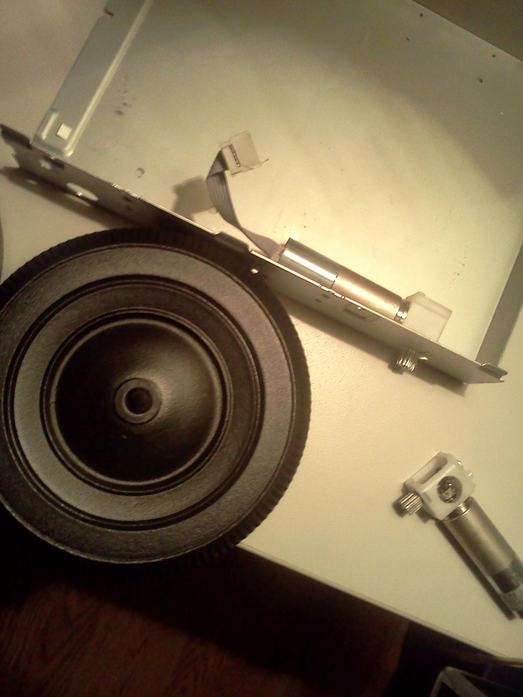

1024 x 1365 - 109K
Comments
That would also lead me to want to to mount the motors outside so that the motor and wheel can be left together as a unit while I'm building and experimenting. This is where even a cheap Harbor Frieght drill press and some quick clamps would help a great deal. Drilling centered and square with a hand drill is near impossible.
I'd be concerned even if you could extend the axle, it would place too large of a sideways torque on the gearbox.
One option would be to use a gear (either the one on it now or replacing it with a different gear), that then drives another gear which would be attached to the wheel. You could also use a chain or a belt to transfer torque from the motor to the wheel. By using gears of two different sizes you could modify the final gear ratio between motor and wheel.
Obviously servos don't have much of an axle for attaching wheels, and I was concerned about the sideways torque on a servo so I used a set of gears to transfer the torque to a more robust axle. Here's one method I've used of attaching a gear to a servo. There are two screws holding the gear to the servo horn.
Here's another example of adding a wheel to a motor without a protruding axle.
I was able to attach a piece of plywood to the face of these AX-12 servos. I think attached the wheel to the piece of plywood.
Besides plywood, I also like PolyMorph and Sugru for connecting robot parts togeter.
If you use a direct drive with the wheels you might want to use some sort of structure on the outside of the wheels to support the axle on the oposite side of the wheel from the motor.
Based on my very limited experience, I'm a bit concerned about the size of wheel your using with that motor. The wheel just seems like it might be too large for those motors. (I'm not sure about this.)
As I mentioned in another thread, I have several of these motors on their way. I'll be sure to pass along anything I come up with for attaching wheels to them. I hope you keep us updated on your efforts.
As far as wheel size goes ive already double sided taped the wheels on the motors they work fine, these wheels are hollow plastic so there pretty darn light.
Last night I was playing around with stuff and came up with this
Thats a 4mm axel, so I could use a 3mm to 4mm, shaft coupler, if I remove the gear. I found this one on ebay but im not sure if its what im looking for it say 3mm x 4mm not 3mm to 4mm, so im not sure. I was also thinking maybe I could get some metric drill bits and cut a piece of wood with a whole saw, then drill a 7mm hole through one side and a 5mm hole through the other, and make my own coupling but im not sure how in the heck I could sink a set screw through wood?