

Sensor / circuit help please?
 Rforbes
Posts: 281
Rforbes
Posts: 281
Hi all,
I'm trying to figure out a sensor circuit and I'm just working myself into a hole.
I'd like to use an AC current switch to monitor an AC load. I don't need to measure the amount of AC current, but I'd like to know when I have current. It's basically a "proving" switch.
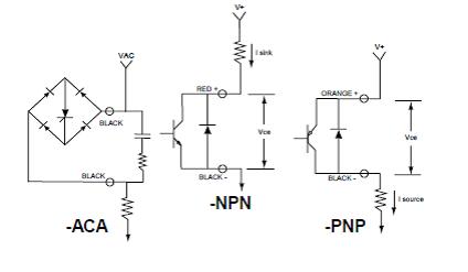
I've attached an image of the connection/circuit diagram for the sensor in question. I can order a PNP type or an NPN type transistor output.
What I'd like to do is drive an I/O pin using the output on this sensor. Whether I drive it high or low doesn't matter, for coding purposes.
The specifications for the output are as follows (from the instruction/data sheet)
Vce (full off): 30 VDC max.
Isink (full on): 120 mADC max.@ rated full-on
Vce (reverse polarity voltage): 1.2 VDC @
100 mADC
Vce (full on): 1.5 VDC @ 120 mADC Isink
Off state leakage current: 5ua @ 30 VDC
(typical)
The output is driven "fully on" when more than 350 mA AC is flowing through the conductor it's sensing.
Will this sensor work if I choose the PNP type, apply 3.3V to the orange lead and connect the black lead to one of the IO pins?
Thanks in advance,
Robert
I'm trying to figure out a sensor circuit and I'm just working myself into a hole.
I'd like to use an AC current switch to monitor an AC load. I don't need to measure the amount of AC current, but I'd like to know when I have current. It's basically a "proving" switch.
I've attached an image of the connection/circuit diagram for the sensor in question. I can order a PNP type or an NPN type transistor output.
What I'd like to do is drive an I/O pin using the output on this sensor. Whether I drive it high or low doesn't matter, for coding purposes.
The specifications for the output are as follows (from the instruction/data sheet)
Vce (full off): 30 VDC max.
Isink (full on): 120 mADC max.@ rated full-on
Vce (reverse polarity voltage): 1.2 VDC @
100 mADC
Vce (full on): 1.5 VDC @ 120 mADC Isink
Off state leakage current: 5ua @ 30 VDC
(typical)
The output is driven "fully on" when more than 350 mA AC is flowing through the conductor it's sensing.
Will this sensor work if I choose the PNP type, apply 3.3V to the orange lead and connect the black lead to one of the IO pins?
Thanks in advance,
Robert
424 x 247 - 10K
Comments
http://www.mouser.com/Semiconductors/Drivers/LED-Lighting-Drivers/_/N-7zhqf?Keyword=HV9921
or maybe wrap the AC cord around a iron bar and put this senor at the end.
http://www.mouser.com/Sensors/Hall-Effect-Magnetic-Sensors/Board-Mount-Hall-Effect-Magnetic-Sensors/_/N-6g7qoZscv7?Keyword=AH180
I'm not sure what you mean, but I think maybe I should have just shown the whole data sheet for this sensor to be a little more clear about my question. So, here it is.
http://www.crmagnetics.com/Products/Assets/ProductPDFs/CR9300%20Series.pdf
I don't understand the "electrical connection" section diagrams well enough to feel comfortable interfacing this sensor to an I/O pin on the propeller. I'm HOPING I can simply use the PNP output version, and connect 3.3VDC+ to the orange lead, and connect the black lead directly to an I/O pin.
When current flows through the CT, it's supposed to "turn on" the output... which would send the 3.3V to the IO pin on the propeller and let me verify that I have current flowing (ie. proving switch)
I'm struggling with two issues here- lack of practical knowledge about the PNP and NPN transistors and overthinking. Can you take a look at the link and tell me what you think?
Thanks
Robert
>The unit is available with a NPN or PNP output transistor
Get a unit with NPN, put a 10k pull-up resistor (one side connected to 3-5V) at location that shows as 'I sink' in pic
connect red wire to to mcu input pin and black to gnd.
The idea is that red gets connected to gnd when current is detected and mcu pin will see a zero
PNP version, 10K pull-down to GND at I-source location, black wire to MCU input pin.
Remember, the logic out is not a Push/Pull (1 or a 0)
but 'nothing' as one state and other state is a voltage from Vcc (pnp) or clamped to gnd (npn)
And we can not have 'nothing' (floating) signal going to a mcu input pin.
This is exactly what I was looking for- a good explanation of how the circuit can be hooked up and why it works like this. I really gotta sit down and learn about the transistor stuff. I don't know why, but it's confusing the Smile out of me. Just gotta keep at it until something clicks I reckon. THANKS!!!
Robert
They are on when you have:
Voltage on a n-mosfet gate pin
Current on a n-transistor base pin (use 2k resistor to limit)
When ON they will complete the circuit to GND.
When they are off it's like leaving the gate open (a switch) e.g nothing.
PNP should be used when you have no other choice but to open the gate the from the high side.