Audio circuit question
 lardom
Posts: 1,659
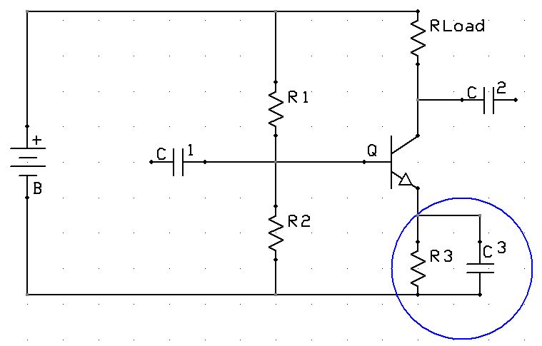
I need help understanding why a resistor-capacitor combination is placed at the emitter of an audio amplifier circuit. It looks like its purpose is to block DC but I don't know since I can't track down a satisfactory explanation. Are 'R3' and 'C3'chosen to handle a specific frequency? Is there a formula?


Comments
-Phil
Yes there is a formula. Drop the circuit into spice, and it will show you
http://www.linear.com/designtools/software/#LTspice
Such a circuit is very 'low budget' as the ultimate AC gain is set by the transistor internal emitter impedance.
Linearity is likewise 'not great'
@Phil Pilgrim (PhiPi)' Thanks. "negative feedback" and "linearity" are concepts I will become acquainted with.
@jmg, thanks for the link.
The capacitor shorts the emitter to ground at AC to vastly increase the gain (its a common-emitter circuit at AC rather than an emitter-follower).
You chose the RC time constant to be larger than one radian at the lowest frequency of interest (ie RC > 0.01 for audio)
[edit: BTW its an awful circuit for audio, very non-linear, this is more often seen at RF and IF. To improve the linearity you'd add another resistor between emitter and the RC pair]
Leaving out for a moment the capacitor C3 and the intrinsic emitter resistance Re, the gain of the circuit is, RL / R3. That is because, to first approximation, the current in the emitter circuit is the same as the current in the collector circuit. For example, if RL js twice the value R3, then any change of voltage across R3 is passed through as a voltage change of twice as much across RL.
The voltage at the emitter of the transistor is 0.6V less than the voltage at the base, which in turn is provided by the voltage divider comprised of R1 and R2. By adjusting that voltage, you are setting the voltage across R3 and therefore also the current in the main path through the collector and RL. Usually you want the voltage across RL to be centered on 1/2 of the power supply voltage, so that the output can swing both ways as an AC amplifier. So, you see, there is a set of relatively simple ohm's law type of equations that tie together the component and power supply values and the circuit DC gain. These establish the "DC bias conditions", the "operating point".
By adding capacitor C3, its reactance in ohms = XC = 1 / 2pi f C is now in parallel with R3. That lowers the effective resistance at higher frequencies and increases the AC current, which also means a higher AC current thru RL, that is, higher AC gain.
Neither the DC gain nor the AC gain can go to zero due to the intrinsic emitter resistance Re. The DC gain is corrected to RL / (R3 + Re). If the current in the emitter to collector circuit happens to be 1mA, the value of Re will be about 25Ω, but its value depends on both the current and on the junction temperature. The amplifier does have maximum gain when R3=0, however, at that point, gain due to changes in Re depends on temperature, and because of that there is danger that the output operating point will move far away from Vcc / 2. The operation is also non-linear due to the additional dependence of Re itself on current. So a resistor like R3 is usually added, unless the circuit happens to be part of a larger feedback loop. In addition, a resistor is often added in series with C3, to limit and stabilize the increase in gain at higher frequencies.
The same reasoning also applies to FET transistor amplifiers. I've glossed over off a lot of details, such as base current and other transistor parameters, but that is a nutshell summary of what goes into designing a single transistor amplifier.
One of the 'new' problems I have is that I saw the transistor as a variable resistor forming an additional voltage divider on the right side of the circuit. It explained why the input signal is inverted but it did not give the reason for 'R3'.
I don't know if I understand this correctly yet but it seems resistors are used to stabilize the temperature sensitive transistor.
I learned a lot by building a few audio preamps that were basically transistor versions of op amps. I got these projects as bare boards from Elliot Sound Products.
http://sound.westhost.com/no-opamps.htm
Elliot Sound Products is a wonderful audio site in Australia and he really tries to explain rather than hype audio. He offers a lot to read and a helpful forum.
sound.westhost.com
Along with all that he sells boards that are easy to mail cheaply world wide.