

LED Strobe light
 GeeksGoneBad
Posts: 100
GeeksGoneBad
Posts: 100
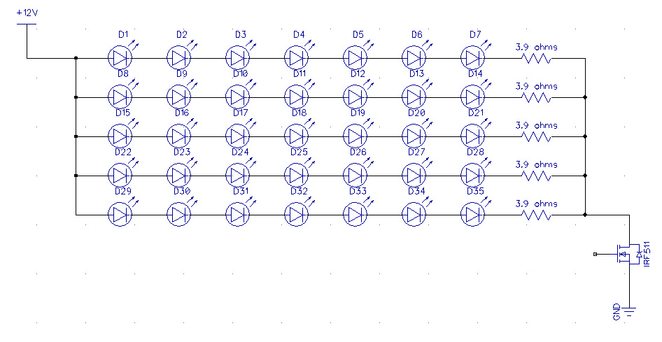
I am thinking I want to make an LED strobe light - I am already using the Propeller in this project so it makes sense to use the prop to fire the strobe?
I *think* this is the circuit I want (I designed it myself so if it's wrong, it's my fault) I have a slew of different mosfets on hand and that's the key word here - on hand - I want to make this by Saturday") so I don't have time to wait for a part to get shipped... I picked the IRF511 just because it was a part that popped into my head - but I would like recommendations on the best thing to use in that spot
so I don't have time to wait for a part to get shipped... I picked the IRF511 just because it was a part that popped into my head - but I would like recommendations on the best thing to use in that spot
yes? No? whatcha think?

I *think* this is the circuit I want (I designed it myself so if it's wrong, it's my fault) I have a slew of different mosfets on hand and that's the key word here - on hand - I want to make this by Saturday
yes? No? whatcha think?
946 x 489 - 157K
Comments
1. Your LEDs better not have a forward voltage greater than about 1.6V, or they will not light. IOW, white or blue LEDs will not work, but you may be okay with red.
2. The IRF511 has too high a gate voltage requirement to be driven from the Prop. (I wish RadioShack would quit carrying them.) A better choice would be an IRF3708. But check the datasheets for the parts that you have. Ignore the gate threshold voltage spec, and look for a chart or table that gives the source/drain resistance for a gate drive of 3.3V.
-Phil
The two MOSFETs in parallel are just to make the circuit simulator I'm using behave better. Anyway, that circuit will dump a large amount of current through the LEDs, but will be limited to the energy stored in the cap. That way, you can safely, severely over-drive the LEDs, and as long as the energy in the cap is low enough, you won't damage them.
Yes basically it should work just fine.
However, that MOSFET the IRF511 can't be driven directly by the prop. It has a 10V gate.
You can make a simple gate driver for the IRF511 with an NPN transistor.
250 ohm on the base with 1.5K on the collector to 12V. Should work but not tested.
You can generate the pulses by:
1. Setup the counters as a numerically controlled oscillator, NCO. (For a Halloween strobe the jitter is inconsequential.)
2. Using software to generate the square wave.
I would use FemtoBasic to output the square wave.
Duane J
Duane J
In your circuit, you need a resistor in each string of LEDs. Otherwise some strings will be brighter than others, due to variations in the the LEDs' forward voltages.
-Phil
So that's why it is done, that's good to know. A fellow forumista pointed me to the LED array design wizard and it always puts a separate resistor on each string. I followed the advice, but always wondered why.
I bought a "12V 3W" LED from dx.com, and when driving it at 15-20mA, I can see significant differences in light level between various diodes within the module. However, when I bring it up to 270mA (design current), the brightness evens out due to the inherent resistance of the LEDs and bonding wires becoming more significant than the logarithmic I/V curve of the diode itself.
GeeksGoneBad: Using red LEDs, you can put 5 in series for my circuit.
Are you sure it's that and not just your rods and cones becoming saturated?
-Phil
I know it's an extra part, but the TC4427 costs about $1.50 and allows you to control the gate voltage well above what the Propeller output provides. We (EFX-TEK) have produced about 2000 of these boards for our customer who is very happy with them.
Secondly junk that ancient part, the IRF511 is not really up to the task (its a truly ancient device too). A logic-level MOSFET with a 0.05 ohm or less Rds(on) spec will be much more suited - you don't want a heatsink do you? Just make sure the LEDs and resistors will take their power dissipations OK.
Another way is to use an LED driver chip (I just happen to have been playing with a CAT4104 recently - resistor-programmable in 100mA to 1A range, 0.5V drop out, 3V3 logic drive compatible, fast PWM compatible, something like 25V max LED chain IIRC - constant current means no resistor needed for one chain. Probably only SMT though.)
unfortunately I have 130 of the IRF511 so I WILL be using them any chance I get LOL
You should be okay with them, as long as you use a gate driver chip.
-Phil
I know I posted it here before but I have my parts all cataloged at http://www.makertrader.com (which is a site I made to keep track of what I have and share with friends)
Yups Mouser shipped my gate drivers today so I should have them - I figure they are just easier to use, right?
I am still a newbee, trying to master the BS2. Something to look at anyway.
Happy New Year