

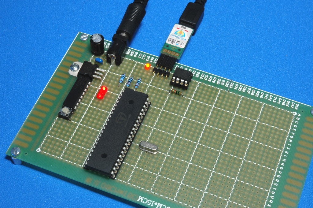
Basic Propeller circuit on a proto board

I finally finished my Propeller Board project, the goal of which was to actually put to use the Propeller chip I received in the 25th Anniversary "Mystery Bag". The first one I made didn't turn out so well, and neither did the second. The third one turned out pretty good though.
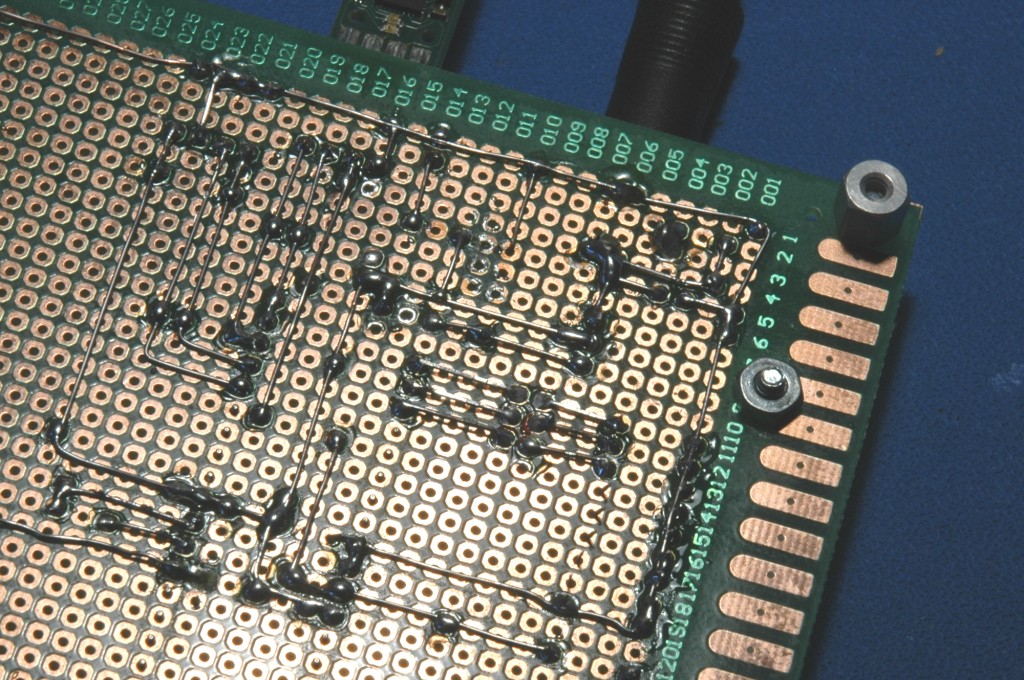
I had never really built much of anything on a perf board/proto-board before. I guess you could just connect everything using pieces of wire running all over the place, but I wanted something a little nicer and neater than that. What I finally ended up doing was to lay out the board as if it was going to be a single-sided PCB. I actually used Diptrace to do this. I put as much wiring as possible on the bottom. I also tried to restrict connections to straight lines and right-angle turns because it makes the entire wiring process a lot easier. It turned out to be not as easy or as quick to build as I thought it would be. Most of the time the wire doesn't like to cooperate and lay flat for soldering, and it's very easy to put a part in the wrong place or wire a connection incorrectly. Still, I'm pretty happy with the result. There is good access to the pins and plenty of empty space left. Maybe I'll add some sockets for the i/o pins and a small breadboard, and I may need to add a 5 volt regulator at some point.

Note that there are some red LEDs and an 8 resistor DIP pack in the photo that aren't shown on the PCB layout.
Those 2 mm LEDs are the perfect size for a board like this or regular plastic breadboards.
I had never really built much of anything on a perf board/proto-board before. I guess you could just connect everything using pieces of wire running all over the place, but I wanted something a little nicer and neater than that. What I finally ended up doing was to lay out the board as if it was going to be a single-sided PCB. I actually used Diptrace to do this. I put as much wiring as possible on the bottom. I also tried to restrict connections to straight lines and right-angle turns because it makes the entire wiring process a lot easier. It turned out to be not as easy or as quick to build as I thought it would be. Most of the time the wire doesn't like to cooperate and lay flat for soldering, and it's very easy to put a part in the wrong place or wire a connection incorrectly. Still, I'm pretty happy with the result. There is good access to the pins and plenty of empty space left. Maybe I'll add some sockets for the i/o pins and a small breadboard, and I may need to add a 5 volt regulator at some point.
Note that there are some red LEDs and an 8 resistor DIP pack in the photo that aren't shown on the PCB layout.
Those 2 mm LEDs are the perfect size for a board like this or regular plastic breadboards.
1024 x 680 - 204K
1024 x 680 - 276K
1024 x 1024 - 154K
Comments
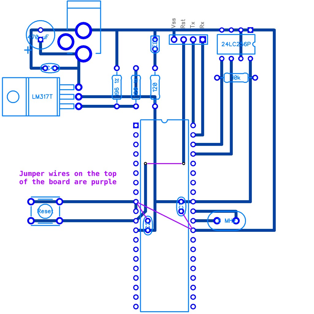
Well, I've been playing around with it and it looks like at least one jumper will be necessary, maybe I can disguise it as a resistor
Also, it turns out that the way I mounted the caps on the power pins is actually kind of neat.
To move them out from under the Prop I'll have to use caps with wider pin spacing.
There are zero-Ohm resistors available that look like conventional resistors, but are just a piece of wire with some resistor-shaped plastic molded on it and zero Ohms coded into color stripes on the body. They're used for automatic part placement where some versions of a device require a jumper and others require a discrete resistance value in the same location.
* There are two other IC's besides the propeller on that board. One is obviously the EEPROM, but what is the other one next to the voltage regulator? It's not on the schematic, so I'm curious.
* I'm surprised to see C1 and C2 on the supply side of the voltage regulator, usually they require capacitors on both the supply and output side.
I agree that building boards is a surprising amount of work. It seems to take me forever.
Unlike LDO regulators, the LM317 doesn't always require capacitors on the output, though it is often a good idea. Once you add capacitors, then you need protection diodes and this increases the complexity of the circuit, which I was trying to avoid. At the low current I expect to draw and the fact that the input is from a regulated switch-mode wall adapter I'm pretty sure it will work fine. I did leave some room for them next to the DC input jack just in case.
You haven't routed any of the I/O to headers or pins or anything. ( :
I haven't added any more LEDs, because I want different colors not all the same, and that will have to wait for the next Mouser order. I also want to have a few of those small tactile buttons somewhere, because I can never get those to fit correctly in plastic breadboards.