

DIY motor feedback from mouse parts.
 rwgast_logicdesign
Posts: 1,464
rwgast_logicdesign
Posts: 1,464
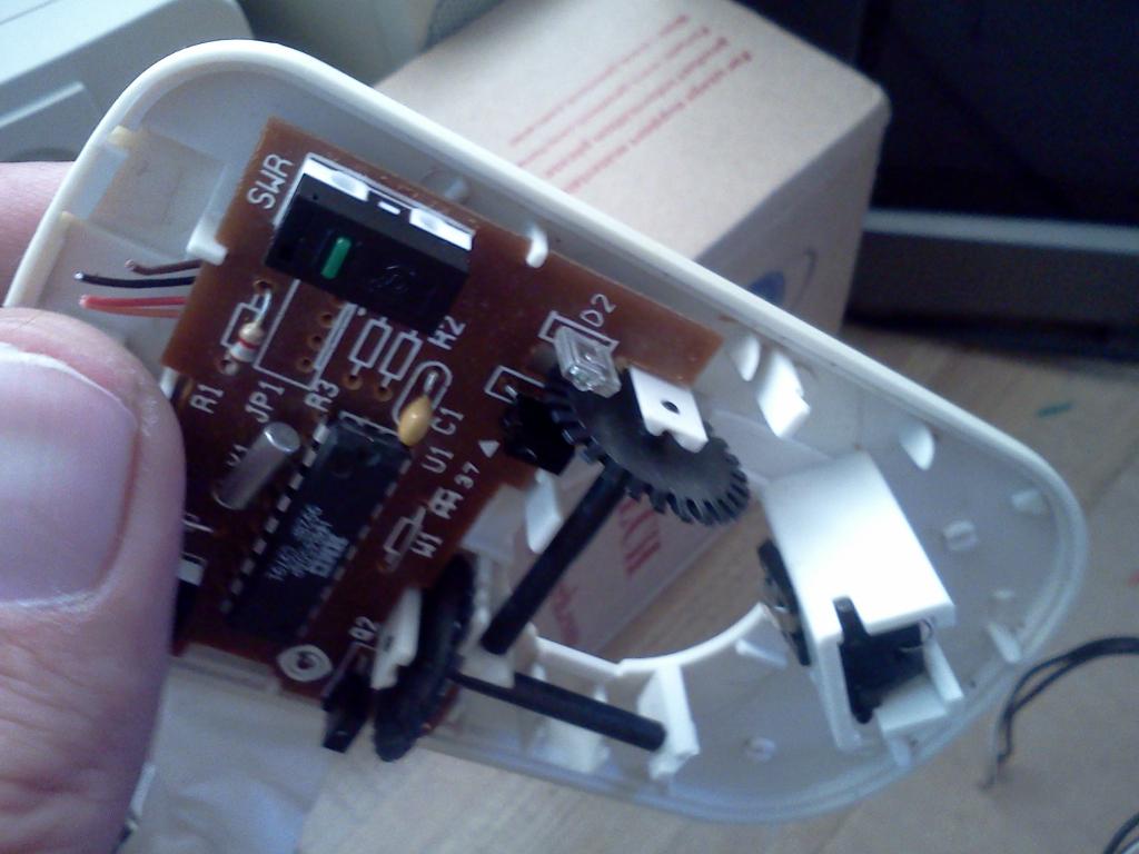
So someone had posted a really cool ink about building wheel encoders from an old ball mouse, which led me even deeper into finding out how to use a laser mouses sensor to track speed and position by running the laser over the floor. Anyways I had an old serial ball mouse so I took it apart to see what could be done with it.
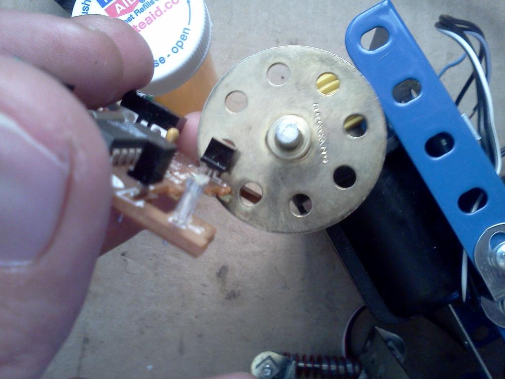
Now what im thinking is I can just cut out the part of the board that contains the IR led and photo transistor, then mount them around an encoder wheel attached to the motor and read the counted pulses with a propeller, this should be easy enough right, the IR stuff in wheel encoder isnt like binary encoded data like an IR remote correct? My biggest issue is that the encoder wheels in the mouse are going to be impossible to drill through the dead center of, Ive tried this with many plastic gears and failed.. So heres what I have and heres what Im thinking about doing..


I really only have four major concerns here, assuming is just as easy as connecting the IR LED and PhotoTransistor to the prop and counting pulses. The first is If I us the brass wheel on the right instead of the wheel with the mouse, will I need to paint it, im wondering if the brass will cause light reflection problems. The next is the resalution, I effevtively jumping from what looks like at least 30 or 40 slots on the mouses wheel to 8 on the brass wheel fitted for my axel and motor shaft size. The resalution also brings up the question of wether to mount directly to the motor shaft or the wheel axels, ive read that you get better resalution if you runn your wheel before any gearing so the wheel spins at a higher RPM, but this seems like more work to get your actual wheel speed. And the last but most important question is will this set up work out side if I dont enclose the encoder wheel and leds in some kind of casing to block out the ambient light?
Is there maybe an obex object I can load on to a prop and connect the leds up reel quick to run some tests? Im assuming the code would be the same for any photo transistor/ir led setup. There is nothing special at all about the hardware correct? I guess im just asking the same thing as above i do not need to decode a 38khz frequency or something correct?
Now what im thinking is I can just cut out the part of the board that contains the IR led and photo transistor, then mount them around an encoder wheel attached to the motor and read the counted pulses with a propeller, this should be easy enough right, the IR stuff in wheel encoder isnt like binary encoded data like an IR remote correct? My biggest issue is that the encoder wheels in the mouse are going to be impossible to drill through the dead center of, Ive tried this with many plastic gears and failed.. So heres what I have and heres what Im thinking about doing..
I really only have four major concerns here, assuming is just as easy as connecting the IR LED and PhotoTransistor to the prop and counting pulses. The first is If I us the brass wheel on the right instead of the wheel with the mouse, will I need to paint it, im wondering if the brass will cause light reflection problems. The next is the resalution, I effevtively jumping from what looks like at least 30 or 40 slots on the mouses wheel to 8 on the brass wheel fitted for my axel and motor shaft size. The resalution also brings up the question of wether to mount directly to the motor shaft or the wheel axels, ive read that you get better resalution if you runn your wheel before any gearing so the wheel spins at a higher RPM, but this seems like more work to get your actual wheel speed. And the last but most important question is will this set up work out side if I dont enclose the encoder wheel and leds in some kind of casing to block out the ambient light?
Is there maybe an obex object I can load on to a prop and connect the leds up reel quick to run some tests? Im assuming the code would be the same for any photo transistor/ir led setup. There is nothing special at all about the hardware correct? I guess im just asking the same thing as above i do not need to decode a 38khz frequency or something correct?
1024 x 768 - 74K
1024 x 768 - 71K
Comments
You can drill a hole in the plastic mouse wheel that will be very close to the center if you use a piece of brass tubing from a hobby store that just fits over the plastic axles of the wheel. Use a dremel with a cutting disk and notch the end of the tubing to create "saw teeth".
The brass wheel may also work since the IR has to go through the holes to reach the detector. Reflections should not be a problem since they are on the other side of the disk from the sensors.
Best to go for maximum resolution so mount the wheel on the motor shaft. You will have to convert pulse counts to distance, and it is the same amount of work wherever you mount it.
I doubt it will be necessary to block ambient light, but if you do it should not be hard to do so later.
ive done alot of research, and am kind of cunfused about encoders though. my plan is to use 1 of each of the optical pairs on its own motor wheel. is this a quadrature encoder? i thought to male a quadrature encoder you had to have two sets of optical sensors on one wheel? also the clear sensor is two leads and the black is 3 these are both photo transistors? the wheels im using are big enough that i could mount the.sensor on the axel as this would be easier since my motors dont have back shafts. i have custom gearing after the motor shaft so while mounting the encoder on the motor shaft will give better resalution im a bit.confused as how i would get an accurate wheel posistion, if i were to mount the encoder by the wheel it should be realtively easy to measure wheel speed and posistion. it seems like this is a resalution vs ease of use issue am right?
back to the question above any quadrature encoder object.should work with this set up? the way i understand it im keeping track of off and ons the black photo transistor out pits, this is the same as grey code.
im sorry ive done alot of looking around but theres so many varied info out there im having a hard time figuring out if what im attempting to build is even a quadrature encoder
No 38Khz modulation means that ambient IR may cause trouble - the encoder needs to be kept away from room light.
There are prebuilt photo transistor/IR led pairs that might be easier to use. Just salvage the mouse's encoder wheels.
Not all mice have encoder wheels like the one's in your photos. I have some that are extremely fine slots and I gave up working with them as they just were too fine to be sure of successful use.
If you want to drill an exact centered hole in the salvaged encoder shaft, cut the shafts off of the existing encoder wheel flush to the wheel. Maybe clean up the cut with sandpaper or a file. Then locate the center and drill a very tiny pilot hole first. Follow up with the right sized shaft hole.
There are two ways to create quadriture encoders. One is to have two sensors in a line and a special wheel with slots or graphics 90 degrees out of phase; the second is to have a wheel with one set of slots and the two sensors 90 degrees out of phase (this means a simpler wheel).
Not impossible. If you don't have a center punch you may want to pick one up. There are some spring loaded one that you can place on your part where you want the hole to be and press down. It will make a small dimple that helps keep the drill for moving around when you start the hole. It helps if you won't have a proper fixture to hold the part or a drill press. You can also start with a very small pilot hole which can be easier to get centered and then follow up with a larger drill. It will follow the first hole you drilled and help keep it centered.
If it is just a single opto sensor or if you only plan on reading one of them then changing the number of slots (or holes) isn't a big deal. However, those optical IR sensors have a pair of receivers and those are setup to match the spacing on the wheel. If you use a different wheel you will mess up the quadrature encoding. Having the quadrature intact is preferred since it will give you both the distance it moved and direction. Otherwise you can only tell that it moved and don't really know which way. I'd recommend using the encoder wheels from the mouse.
If you are making your own home brew encoders then I recommend using two separate encoder channels with the sensors stacked vertically. That way you can change encoder wheels at will without readjusting the sensors. If they are mounted side to side then the spacing between them does matter and you may need to adjust them when changing the encoder resolution. If you search on the encoder threads I've posted on you can get more details on that issue.
There are some objects in the OBEX for encoders. No 38Hz required. You make need to add some sort of cover to block out ambient light but that is about it.
Robert
Almost. Either one by itself can be used for counting. Both of them acting as a team can determine counting and direction.
Here are a few more places you can read up on Quadrature encoders:
http://www.robotoid.com/appnotes/circuits-quad-encoding.html
http://prototalk.net/forums/showthread.php?t=78
http://www.ni.com/white-paper/4763/en
http://www.ni.com/white-paper/7109/en
http://tutorial.cytron.com.my/2012/01/17/quadrature-encoder/
This is a transmissive sensor, so from a IR path viewpoint, you do not need to paint it.
From a stray light path angle, maybe paint would help, but it needs to be IR absorbing.
The sensors in the Mouse are spaced close together (eg usually one half the gap width in the mouse wheel)
- a larger-hole wheel will work, but it will not give linear steps per edge
Yes, enclosing will be essential.
I had a translucent wheel mouse once, that failed on a sun illuminated desk.
It needed baffles added internally, to block the light.
This is where those large holes may cause the most problems - they let a lot of light in.
A better wheel, could make light shrouding easier.
What about a PCB disk, where you drill smaller holes in a CAD generated circle ?
You get full NC control of all dimensions.
Black solder mask is readily available.
jmg that is a reall good idea, all my shafs/axels are 5/32 this would allow me to create dead on deminsions for gears and wheels like you say, i was acually gonna see what a machinest would charge to recreate my encoder wheels from the mouse with the right center whole but this is better. seed will do 10 pcbs for 20 i could then use flat black rubberizing paint on them. i could also use small round holes and etch myself.
what exactly would happen if i made my own wheel via pcb and then used the mouse sensors.. how does a dofferent style wheel throw the ir off
http://forums.parallax.com/showthread.php?138600-Source-for-white-plastic-8.5-quot-x11-quot-printer-sheets
It also talks about the sensor placement. If you just have one set of encoder marks then the placement of the sensors matter in order to get the proper 90 degree offset. By using twp sets of encoder marks 90 degrees out of phase you can place both sensors vertically at the center of each track. They don't require any special adjustment when changing resolutions.
This thread has a list of tools to make your own wheels:
http://forums.parallax.com/showthread.php?138597-Encoder-generators-Quadrature-etc.&highlight=encoder
You can either print them on white material and use the reflective sensors or print them on transparency material and use the pass through type.
Easy enough to try, I'm sure you have PCB with some holes in it somewhere
The wheels tend to have rectangular slots, whilst round holes are more practical in a PCB.
The starting hole size to try, is around 2x the sensor pitch, with the same web width.
Then, if you are a purist, you adjust that slightly, to compensate for the radii, and illumination angles etc, until you get 90' per quadrant.
On the interrupters I have here, you can see the optical active area (size and offset) if you get bright light on the right angles.
Figure 1 in the attached diagram is the basic circuit of the detector. A quadrature encoder needs 2 such circuits placed so the output pulses overlap.
In figure 2 the spacing between the black and transparent sections of the wheel is such that the two signals are approximately 90 degrees out of phase. When detector A goes from low to high you can determine the direction of rotation by the level on detector B. The wheel is going clockwise if B is low, counter clockwise if B is high.
In figure 3 the spacing between the black and transparent sections of the wheel is such that the two signals are approximately 45 degrees out of phase. The actual phase angle is not critical as long as the signals have some overlap. The phase angle must be more than 0 degrees and less than 180 degrees.
Figure 4 shows a combination of wheel and detector spacing that will not work for determining the direction of rotation.
Also im about done making this setup, gonna drill the holes in the encoder wheels now (crossing fingers i get it right) but what im unclear on is what is the resalution on my encoder is it the number of empty slots in the wheel or the number of empty slots and filled in spots, and does using two photo transistors effect how you derive resalution>
https://www.sparkfun.com/products/241
This above link might help, but I suspect only the LED is critical. Most transistors, including photo-transistors will tolerate much higher voltages than they have in actual use.
Personally, I think you are getting involved in doing this in a rather difficult manner.
1. The parts in a mouse are very tiny.
2. The parts are undocumented
3. For quadrature, you are going to have difficulty getting everything positioned right with such tight tolerances due to using small salvaged parts.
There are other IR photo sensors that would make a build easier and one could use a bigger disk. Or, one could use magnets and hall-effect sensors.
Take a look at a 'photo interrupter'. http://uk.farnell.com/jsp/search/productdetail.jsp?SKU=2079961&MER=baynote-2079961-pr
Or you could use an IR photo reflective sensor, like the CNY70
http://www.vishay.com/docs/83751/cny70.pdf
Refer to Diagram 2 for the following explanation (the wheel is turning clockwise):
Both sensors are under a transparent area of the wheel so both outputs A & B are low.
The wheel turns 1/16th of a turn. Sensor A is blocked so it's output is high, sensor B is clear so it's output is low.
The wheel turns another 1/16th of a turn. Sensor A & B are blocked so both output are high.
The wheel turns another 1/16th of a turn. Sensor A is now clear so it's output is low, sensor B is still blocked so it's output is high.
On the next 1/16th of a turn both sensors are clear again and the sequence repeats.
It does not matter if the wheel has alternating dark and transparent spokes or holes and solid areas between the holes. As long as the areas that block or allow the ir to pass are at least wide enough to cover both sensors. That is why figure 2 and 3 will work as quadrature encoders and figure 4 will not.
The resolution on the encoder in figure 2 can be one of the following:
If you only count the pulses from sensor A it is 1/4th of a motor revolution.
If you count each transition (high to low/low to high) from sensor A it is 1/8th of a motor revolution.
If you count the transitions from both sensors it is 1/16th of a motor revolution.
What that means as far as a robot movement depends on the motor gearing and wheel diameter.
http://physlab.lums.edu.pk/images/1/10/Photodiode_circuit.pdf
Only 2 leads is a photo-diode.
or a photo-transistor with no base connection. There is a difference.
First of all let me make sure I under stand this right, I should have two ouptuts from the photo transistor, and they should be either hi or low depending on if the IR beam is broken? If this is wrong its probably causing alot of my confusion. Im thinking the transistor should be outputting a square wave signal from it emitter and collector for the speed and position.
The way the pTransistor is layed out also makes no sense to me, the base is grounded, im not awesome this transistors, IO have succesfully used transister to amplify LEDs and invert signals none of the transistor circuits I have ever made have the base grounded. The middle pin of the pTransistor ties to the ground of the IR LED and then goes off to the ground on the mouse button. Does this appear to make sense to anyone?
I can also get the reflective type sensors from vishay and print my own wheels, but I dont like this idea beacuase I eventually want this bot out in the dessert and I feel like a paper wheel is not very rugged... Is there any advanage to using the reflective encoders? Also on a slot interupter how does the apature size effect the sensor I got a 1mm apature since it was the biggest and holes in my encoder are rather large
Now I have ripped my bot up becuase It wasnt a very upgradeable design Right now the final idea is to have a 8 wheel bot that is normal four wheel drive with two more set of wheels mounted higher than the other 4, these axels will be the very front and back set of wheels, I want to drive these off angled wheels with hi torque stepper motors the idea being that when the bot get stuck on a rock or incline I can use the steppers to help dig it out/pull it over the rock. For this design id like something solid for wheel encoding but also cheap and easy to use since I will need 4 encoders total, I have been looking at eventually upgrading too these and would like an opinion
http://www.ebay.com/itm/Oak-Grigsby-900-400-Optical-Encoder-2-CH-Quadrature-Robotic-Hobby-CNC-Avail-Qty-/140868604833?pt=LH_DefaultDomain_0&hash=item20cc6c53a1
they seem nice and are enclosed in steel so they aren gonna get dirt in them but im not sure if these are worth buying or not, most othere systems are in the 30-60 dollar range
You can make your own encoder with the brass hub and the Vishay slot interrupters but the spacing of the interrupters is critical. The output pulses from the 2 interrupters must overlap as shown by the wave forms in figure 2 or 3 of my earlier post. The interrupter package may be so wide that you need to mount them over separate holes in the brass hub. This is not a problem as long as at least one of the interrupters position can be adjusted to get the timing right.
I thought more about the reflective sensros I guess I could easly print out a wheel and then paste it to my hub, but im not sure what the benefits of reflective vs slot interrupt are if any. I went ahead and got 4 cny70 reflective sensors and 4 slot interrupters so I could do two motors with either method.
Those notes were incredibly helpful acually the photo trnsistor you drew in the bottom right is what these mice seem to use you cant tell the difference from front and back the middle is ground connected to the IR leds ground. The two outer emitters went directly to the mouses controller IC. So how do I wire those up, if the middle pin is grounded and I then sit in a dark room and interupt the connection what should happen, in my case one emitter is 0v the other 3v (im using a 3.3 supply) when I interupt the signal nothing happens on a DMM. Im not even trying to use the wheel yest just read the emitter pins when I manually break the signal. Im pretty sure the transistor needs to be biased but I dont see that happening on the original board, although I cut it up pretty bad...
FYI, the signal out is not really a square wave. It rises as the ir beam is unblocked and decreases as the beam is blocked. In commercial encoders a schmidt trigger is used to square it up.
The 555 idea agfa mentioned works well for cleaning up the signal.
I managed to pull another photo interrupter out of a disk drive close to the ones I ordered from vishay, I figured I could just play with it until my real sensors with a data sheet get here from vishay
I bought this http://www.radioshack.com/product/index.jsp?productId=2049723 a while back and there wasnt to much data on these leds, apparently the detector is the clear one. I bought these for a remote project not realizing i needed a 38-50khz detector for most applications. Obviously this could work as an interupter if I were to focus the leds at each other and sheild the light, but I was wondering If I could do something cooler with these like set up a beacon, IR object detection, or even better could I focus these at the groung to get an X,Y like a mouse? Im really intrested in the parallax or any mouse module but im not sure I acually want to buy any of it becuase id like to make something high powered enough that works 1 to 6 inches above the ground.
That set from Radio Shack should work. You could use heat shrink tubing to cover the body of them to help direct the beam. The early Rhino XR-1 used pairs similar to these (except the smaller T-1 size) to build their encoders. The easiest circuit for you to use is probably the 2nd one down on Gordons page here:
http://www.robotoid.com/appnotes/circuits-quad-encoding.html
Other than the resistor values it uses the same circuit that I use on my own home built encoders. It uses one gate of a 7416 chip to help clean up the signal. I've been using the 74HC16 chip for this. If you have two quadrature encoders you end up using 4 of the 6 gates in the chip. Since it is a CMOS chip you need to attach the inputs of the two unused gates as well. I usually just connect them to ground. You never want to leave any unused inputs on a CMOS chip floating (unconnected).
Before you put any of these on your robot I would strongly suggest that you build one as a sample and just do some bench testing with one set. Once you get that working you can build the second one and install them.