Low-Cost DIY Propeller-Board with overcurrentprotection
 StefanL38
Posts: 2,292
Hi,
at the school where I'm working as a teacher I designed a propeller-experimentation-board with overcurrent-protection.
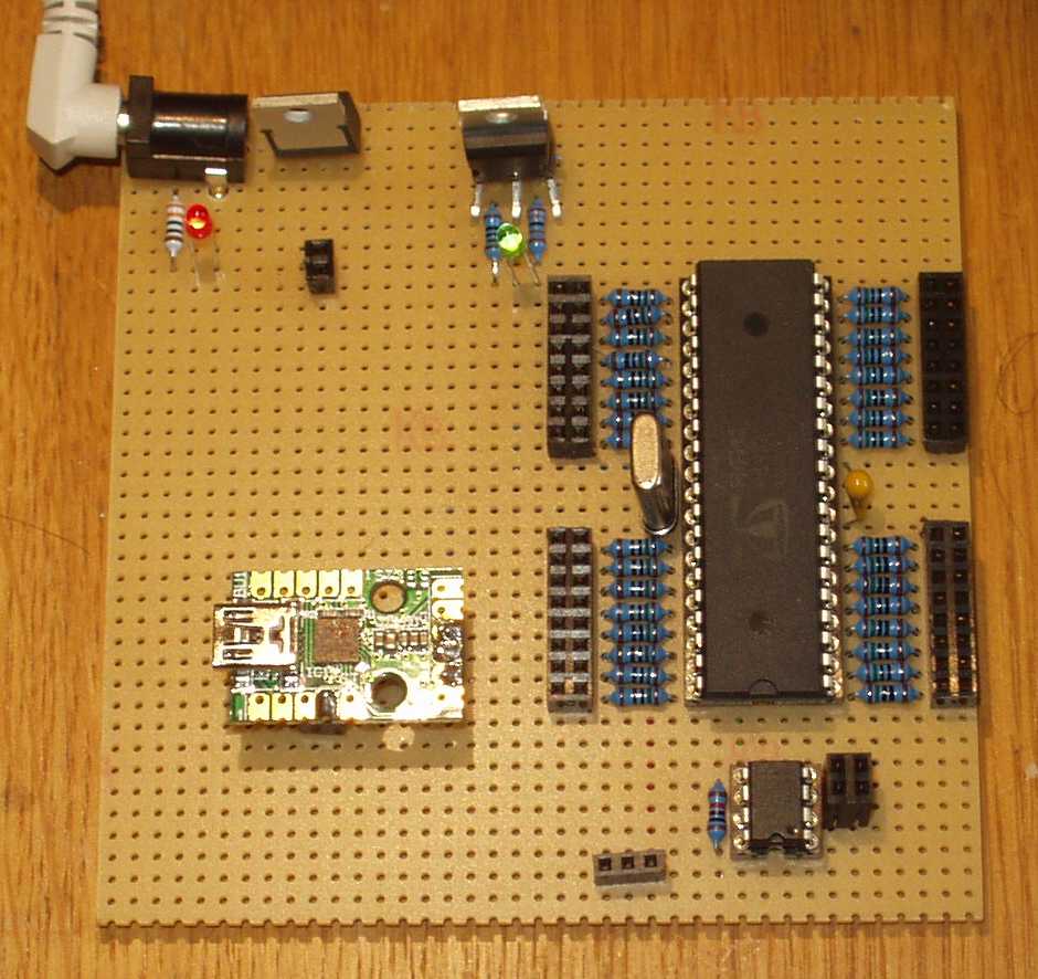
Near the red LED there is a 1,5 A LM7805 fixed voltage regulator.
The one next to the green LED is a L200. Datasheet http://www.st.com/internet/analog/product/67043.jsp
This device can be adjusted in voltage and current-limiting. The resistors near to it adjust the voltage to 3.3V and limit the current to 250 mA.
This protects the whole chip from beeing overloaded.
The blue resistors next to the Propeller-IO-Pins are 150 Ohm current-limiting resistors.
Propeller-IO-Pin
150 Ohm----black-socket. These resistors protect each single pin against overcurrent.
Whenever an IO-Pin schould be connected to GND or +3.3V accidently from the black socket,
the maximum current that can flow is 3.3V / 150 Ohm = 22 mA which is below the 30mA each IO-Pin can stand.
Standard 20mA LEDs can be connected without any addtional resistor because the 150 Ohm resistor already limits the current for the LED.
Still any kind of digital device working with 3.3V can be connected without any problems. Even the resistor-DAC for TV- and VGA-signal are still possible as the value 150 Ohm
is lower than the lowest DAC-value. You just have to substract the 150 Ohms from the standard values and put these resistors in serial with the 150 Ohm.
Only the delta-sigma-ADC will not work as this circuit requires shortest possible connection to the propeller-chip.
The small PCB is a USB-2-serial-adapter that uses the CP2102-chip. It is working reliable for several months on about 10 boards I made in this style.
http://www.elv.de/mini-usb-modul-um2102-komplettbausatz.html
underneath the the small PCB is the 0,1µF reset-capacitor. Next to the propeller-chip you can see a 1µF capacitor. The second one is underneath the propeller-chip
in the middle-space of the 40-DIP-socket.
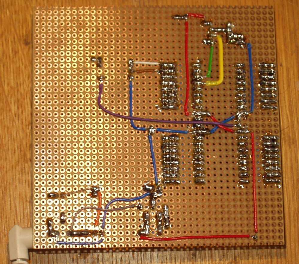
On the downside you can see that I used different colors for wiring. This makes it easier to identify which wire is what.
The small sockets are +5V, +3,3V and GND to connect jumperwires towards a breadboard.
It is important to connect both Vdd and both Vss pins of the Propeller-Chip to the powersupply.
(see the cossed red and blue wires in the middle)
The EEPROM is connect with a green and yellow wire
the serial interface with a white and brown wire.
It takes about three hours to solder everything on the PCB.
So there is all you need to start propellering (Prop-Board, USB-adapter, 9V powersupply) for about 25 euros
with integrated overcurrent-protection.
Please comment on my design: What would you design different? What would you add to the board?
best regards
Stefan


Comments
What a great board/project for an educational environment! You covered every thing I would have thought of!
That looks really fantastic! Is there room for a small bread-board between the usb connector and the power input? Great job!
Paul
Great looking board. If I were to add something it would be pin numbers on the connectors to minimize potential for error when wiring up circuits.
Parallax has this one in the store : http://www.parallax.com/Store/Microcontrollers/PropellerAccessories/tabid/786/CategoryID/85/List/0/SortField/0/catpageindex/2/Level/a/ProductID/571/Default.aspx
Keep up the good work
CogSaver
I like the idea of 150 ohm resistors on the inputs, I'm going to add that to the next version of my first failed attempt at a Propeller board.
One question - what is the reset-capacitor ? I didn't see anything like that on the reference schematic in the propeller manual, or on the QuickStart board schematic.
Me-myself I'm thinking the board is OK for its purpose but not really "great"
At school I'm using a normal-size-bread-board for just 3 €.
I found a very cheap source for jumper-wires (in germany)
http://www.watterott.com/de/Jumper-Wires-Breadboard
@Rick:: you are right the prop-plug doesn't need a reset-capacitor. If you look into the datasheet
under 2.3.2.Alternative Serial Port Connection that uses simple transistors.
This circuit has a reset-capacitor. The reset-input needs just a transition low-high-low and that's what the capacitor is delivering.
Other forum-members have written resetting works without the capacitor.
best regards
Stefan
I just recently learned that you are a teacher, which I consider a very noble profession. Please keep teaching those knowledge hungry minds. Anyhow, you asked:
I would add a microSD card reader.
Bruce
I used SMD versions in the past (0805 footprint), don't know if there are also TH versions. Anyway if you feel daring enough to try to solder an 0805 footprint between the holes of a perf board you could discover it is much easier than anticipated...
Massimo
I really like your design.
Massimo