

Can someone identify this chip
 abicash
Posts: 1
abicash
Posts: 1
Hi forum
My first post!!")
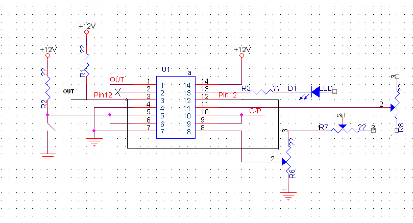
I have been trying to repair an instrument and i am unable to identify a 14 pin chip.
I am attaching an image of the connected parts to this chip.
If someone could give me some pointers , i would be extremely glad
Thanks for your time
My first post!!
I have been trying to repair an instrument and i am unable to identify a 14 pin chip.
I am attaching an image of the connected parts to this chip.
If someone could give me some pointers , i would be extremely glad
Thanks for your time
809 x 437 - 16K
Comments
Welcome to the Parallax forum! What a great puzzle! My knee-jerk first impression was a 556, but the pinout just doesn't jibe. Another was a quad op amp. Though a tantalizing possibility, the pins aren't in quite the right order for that, either.
-Phil
First, the power to the chip is +12 volts. There are logic chips that will accept this, but most are +5 or +3.3 these days.
Second and more importantly, there is a potentiometer in series with a second potentiometer that appears to do nothing.
That second item will either define this a genuine or prove this is nonsense. There are very few good functional schemes where two potentiometers are in series. So what is the purpose of that. And why not just have a resistor for the second one that appears not to use the adjustment on it?
The fact that there are no values and all devices are either resistors or switches makes me wary. One has to decide at some point if the chip is digital, analog, or hybrid.
I suppose one could investigate by trying to create a template of all 14 pins - two are power, and the others would all be either inputs, control, or outputs.
This chip has the clock triggering occurring at a voltage level so the pots could set the voltage level....
So one pot would be 'rough tune' and the other would be 'fine tune'. But a 74LS107 requires less that 7 volts.
Is one a big 'knob' and the other a small PCB-mounted 'trim' pot, maybe?
I would really like to see a picture of the PCB, or the entire device, really.
A closeup of the IC (showing any markings) would also help.
This is 14 pins and operates at up to 20 volts, but I dunno.......
http://www.datasheetcatalog.org/datasheets/105/109379_DS.pdf
Lawson
-Phil
Texas Dynamics De-Ionization Nebulizer IC
Can we narrow it down by elimination?
First of all it isn't a hex buffer or inverter as those have 6 pairs of i/0 and two power lines - a 16 pin dip.
It is not a standard op amp chip (or is it)
It is not a UNL darlington array as those have all outputs on one side and all inputs on the other.
It could be a logic chip with multiple inputs and a sign output of some sort and multiple.
Lets see. 14 pins minus two for power leaves 12. Either 3 devices or 4 devices or 2 devices.
3 devices of 3 ins and 1 out
4 devices of 2 ins and 1 out
2 devices of 5 ins and 1 out
Or 6 device of 1 in and 1 out. ? Wait a second I said that a hex device requires 16 pin dips. I made a boo-boo.
-Phil
Or, it may be incomplete or not entirely accurate. If the existing part is soldered to the board then there may be hidden traces underneath, etc. Could be that 12V is a guess on the supply voltage. We could use some more details. What is the instrument? Is a custom home brew design or something more finished? What is the model #? Can the person provide any pictures? Close ups of the chip and board would help. Are there any markings on the chip or was it all sanded off to hide it?
We will just have to wait and see.
A Snipe hunt to see how many manhours he can waste?
I prefer a good wild goosechase myself.
It's not a CD4051, '4052, '4053, or '4016/4066.
-Phil
-Phil