

Using a motor/wheel to charge batteries, or will physics cancel benefits?
 rwgast_logicdesign
Posts: 1,464
rwgast_logicdesign
Posts: 1,464
Ok so this is kind of concerning a robot design but in reality this is more of a general physics question.
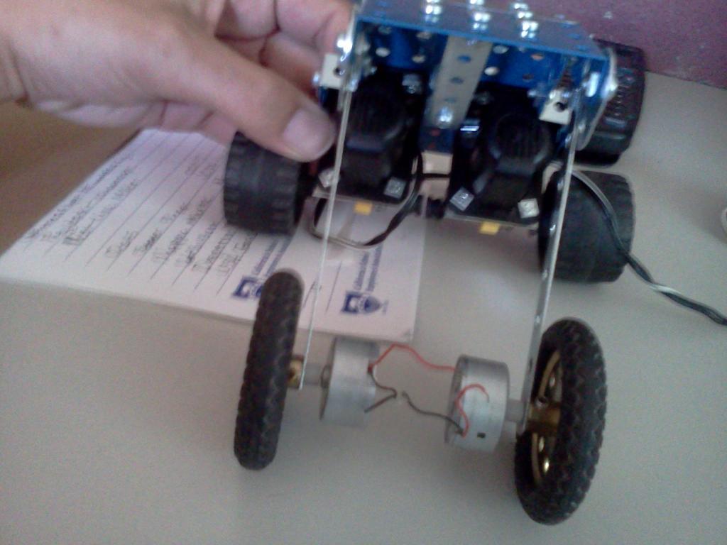
So I needed 4 wheels on my robot to get over bumps 3 wasnt cutting it, and i didnt have 4 matching motors. I thought the answer may be to use two smaller motors attached to the second set of wheel. Basically the idea being these wheels arent powered, the only time any power is sent to these small dc motors is when the bot is turning to give it a little help. So im thinking wow these little motors seem to be generating 3v and 20ma by hand twisting the shaft. So when the bots not turning and the back motors are just pushing the front wheels attached to these little motors why not use that that energy to charge a battery? Im not counting on this being some perpetial energy set up or something just want to know if the friction the motors cause is going to cancel any charging effects. Here is a pick to make it more clear, this is in NO WAY the final set up just a quick picture to visually explain. Also would gearing cause even more friction, just simple spur gears?

So I needed 4 wheels on my robot to get over bumps 3 wasnt cutting it, and i didnt have 4 matching motors. I thought the answer may be to use two smaller motors attached to the second set of wheel. Basically the idea being these wheels arent powered, the only time any power is sent to these small dc motors is when the bot is turning to give it a little help. So im thinking wow these little motors seem to be generating 3v and 20ma by hand twisting the shaft. So when the bots not turning and the back motors are just pushing the front wheels attached to these little motors why not use that that energy to charge a battery? Im not counting on this being some perpetial energy set up or something just want to know if the friction the motors cause is going to cancel any charging effects. Here is a pick to make it more clear, this is in NO WAY the final set up just a quick picture to visually explain. Also would gearing cause even more friction, just simple spur gears?
1024 x 768 - 70K
Comments
Try spining one of the motors without a load and then spin it when the using the motor as a generator to power another motor or light. The motor/generator is harder to turn when there's a load connected to it.
While a motor generator by itself will create some friction, the resistance to turning will greatly increase if the motor/generator is trying to charge a battery.
Edit: Once again, Duane Degn types faster than me! For real fun, connect your motor leads together (short 'em out) and spin the shaft. Dynamic braking at its purest. Very handy in certain situations.
The same effect is used by controllers that use back EMF to measure motor speed -- the current "output" during the off times of the PWM is measured and converted to a motor speed.
The commercial boards may have schematics and documentation that can assist you if you want to roll your own.
E.G.,
http://www.pololu.com/catalog/product/1495
Everything you add causes more friction, even those motors non-driven, so the ideal is a clutch that can decouple dead loads.
More familiar to me (or at least my back) is the circuit on the GE AMX 4 series of portable x-ray units. When the motor drive gets the stop command, the motor windings (PM DC motors) are dropped via relays across a set of power resistors. The current induced in the windings as the unit coasts to stop opposes the motors turning causing more rapid stopping. I mention my back here because when having to retrieve them from a pt room or floor for repair there is a magfriction brake release to enable pushing the unit. Pushing these still requires enormous effort or quite a bit with two people due to the dynamic braking effect. I now disconnect the drive belts as soon as the device is clear of patient areas and then push it the rest of the way.
So the charge you generate will cost energy from the driving wheels plus friction plus charger losses etc. Better to open circuit the motor so that you don't generate current in opposition to the motor turning.
Just a thought.....
Same principle is used on cranes and other devices to control speed such as when lowering a load.
Just saw erco's edit.....
Any energy produced by those motors ultimately comes from the battery by way of the motors driving the robot. With some of that energy lost to friction, IR losses, and conversion losses you are actually increasing the drain on the battery. The only gains are through regenerative braking when stopping or slowing the robot when going down hill, and you are only gaining a portion of the energy used to accelerate the robot or drive it uphill in the first place.
Yep, the experts say it can't be done, however, over the years, I have developed a theory that I sure would like to test. My only problem is that it will cost me at least $2000 to test the theory. I am sure it would be wasted money, but I also know it would be very interesting to construct and perform the testing.
I tried a couple experiments in the past trying to obtain the free lunch, and I must say they were very interesting to say the least.
The are no problems, only solutions
Bruce
You don't get power between PWM pulses that is usable to charge batteries. (Edit: At least I really don't see how they could without requiring even more power from the batteriy during the pulse on time.)
As Kwinn and others have mentioned the regenerative charging happens during braking (by using the motor as a gererator which acts as a break) or going down hill, where again, the motor is used to slow the car. You can't charge the battery without slowing the car.
We had a demo of this in a physics class. A string was wrapped around a wheel and attached to a weight. When the weight dropped the wheel and generator turned quickly. The generator was connected to a light socket (load). Without the light bulb the weight dropped very fast since the generator just had to overcome its own friction. By adding a light bulb to the circuit, the weight dropped much more slowly.
A free spinning generator isn't nearly as hard to turn as one with a load (light bulb or charging circuit).
As I mentioned above you can test this yourself. Wire two DC motors together so one motor is being used to power the other motor. Now when you spin the first motor the second motor will also spin. If you hold the second motor so it can''t spin as freely, the first motor becomes much harder to turn. Holding the second motor is similar to adding a charging circuit to the first motor. It acts as a break to resist its motion.
Ouch!
Make it stop! MAKE IT STOP!!!!!!