Got 60Hz or 50Hz interference?
 Beau Schwabe
Posts: 6,576
Just thought I would pass this along... I am working on an application that doesn't like the 60Hz that is inevitable all around us. Just wanted to show some unloaded scope views of the effects of what a simple filter can accomplish. This filter is often referred to as a twin "T" notch filter, and as far as passive filters are concerned twin "T's" are pretty darn good.
Note: values are given in the schematic that would provide similar results for a 50Hz grid.
Schematic: (Note: in this case, the antenna was my finger)
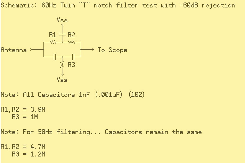
Image capture with the Filter ground (Vss) removed. Notice the 62 Volt Pk-Pk voltage
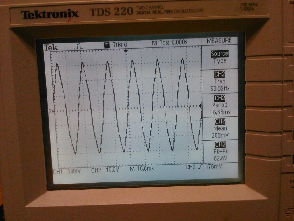
Image capture with the Filter ground (Vss) applied. Pk-Pk has been dramatically reduced to 2V
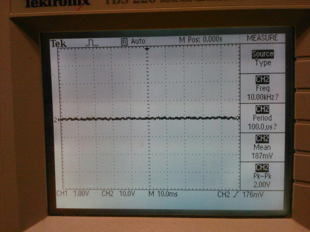
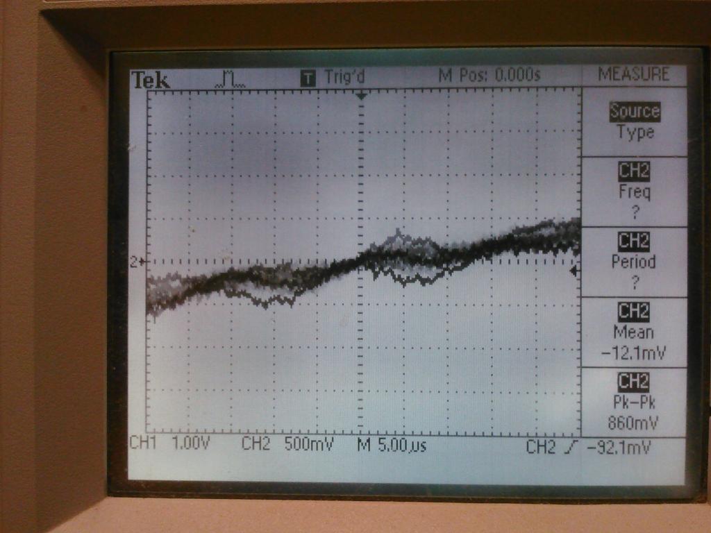
Image capture with the Filter ground (Vss) applied. Same as above but zoomed in. Pk-Pk value is even lower (slight more loading from the scope? ... Perhaps?) ... but you can see the "other noise" much better without being swamped with 60Hz.
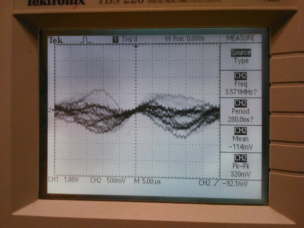
Image capture with the Filter ground (Vss) removed. Same zoom in as above. Notice the 60Hz taking over the ground slope. If I kept zooming out I would eventually have the same view as the first scope image.
Enjoy!
Note: values are given in the schematic that would provide similar results for a 50Hz grid.
Schematic: (Note: in this case, the antenna was my finger)

Image capture with the Filter ground (Vss) removed. Notice the 62 Volt Pk-Pk voltage

Image capture with the Filter ground (Vss) applied. Pk-Pk has been dramatically reduced to 2V

Image capture with the Filter ground (Vss) applied. Same as above but zoomed in. Pk-Pk value is even lower (slight more loading from the scope? ... Perhaps?) ... but you can see the "other noise" much better without being swamped with 60Hz.

Image capture with the Filter ground (Vss) removed. Same zoom in as above. Notice the 60Hz taking over the ground slope. If I kept zooming out I would eventually have the same view as the first scope image.

Enjoy!


Comments
-Phil
We had 50Hz problems with a video terminal released back in 1976. It was designed in the USA and they could not replicate the problem because of 60Hz. I inserted an rc filter in the video section (IIRC the horizontal circuitry) to mostly remove the problem. Untimately though, it was accomplished as filtering around the power transformer, and basically my mods as well. BTW it was one of the first terminals to use the new Intel 8008 micro and 1702 eproms. My how things hve progressed!
Lawson
I think theoretically the circuit has infinite Q whatever the component values - there is a filter zero slap bang on the imaginary axis. Slight imbalances in component value take the zero off axis and reduce the Q to finite values. To allow the reponse to be flat away from the notch you want low-impedance components, but that effectively reduces the depth of a real-world notch if taken too far. Do I make sense?
I haven't got a clue what you're talking about. I slept through those lectures -- boooooring! -- and none of it was on the final exam.
-Phil