

Need input, suggestions, tips, on the mechanical side of building a robot chassis.
 rwgast_logicdesign
Posts: 1,464
rwgast_logicdesign
Posts: 1,464
Ok so I've decided to start a robot project. This is going to be more of a long term thing. Ive got alot of ideas for how I want to implement software and electronics side of things thats not really what this post is all about though, its more about the mechanical side of things, and buiding the actual shell for the bot.
So im not trying to spend alot of money in the begging I have alot of old erector sets, with plenty of pieces. This is how I will be building the chassis/frame that decision is final at the moment for a few reasons. First of all its free, Second of all I don't want to sink money into any type of chassis and the realize its not what I wanted. Right now im just looking to build something practical not a walker or anything.
Right now im looking into two different designs using wheels but im not sure the best way to implement them. The first thing im thinking is just a regular four wheel design with front wheel drive. The problem i have with this design is being able to make tight turns inside, and how exactly you would build the drive train. Im thinking some kind of motor to turn the wheels, and maybe a servo with the horn facing the ground to make the front wheels turn accurately. Im not sure if that is even a good design or not but its the best I come up with with based on off the shelf cheaper parts.
The second thing im thinking is a bot that spins to turn. I guess the way you make these do a spin turn would be to control certain combinations of individual wheels, going forward and reverse on opposite sides of the chasis. But what i dont understand is how these go forward, im talking about the kind of bots with more than 2 wheels not the balancing ones, something like this
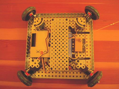
I also see alot of bots with four wheels but I dont understand how they turn, these rolling type platforms would work well too, I guess my first idea would be like this but with front wheels that turn attached to a servo the same way this ping sensor is in this picture
Im also wondering what the best way is going to be to get the wheels to spin, im thinking a decent motor and with an h bridge and pwm. But i see some people using servos or stepper motors to turn the wheels. I dont understand why you would do that unless you need the bots drive train to be super accurate, it seems less powerfull and more exspensive.
Basically I just want a rolling platform that is decently mobile like an RC car outside, and can make tight turns inside. Nothing exotic like a balancing bot or walker, and not a three wheel platform for many reasons,
So im not trying to spend alot of money in the begging I have alot of old erector sets, with plenty of pieces. This is how I will be building the chassis/frame that decision is final at the moment for a few reasons. First of all its free, Second of all I don't want to sink money into any type of chassis and the realize its not what I wanted. Right now im just looking to build something practical not a walker or anything.
Right now im looking into two different designs using wheels but im not sure the best way to implement them. The first thing im thinking is just a regular four wheel design with front wheel drive. The problem i have with this design is being able to make tight turns inside, and how exactly you would build the drive train. Im thinking some kind of motor to turn the wheels, and maybe a servo with the horn facing the ground to make the front wheels turn accurately. Im not sure if that is even a good design or not but its the best I come up with with based on off the shelf cheaper parts.
The second thing im thinking is a bot that spins to turn. I guess the way you make these do a spin turn would be to control certain combinations of individual wheels, going forward and reverse on opposite sides of the chasis. But what i dont understand is how these go forward, im talking about the kind of bots with more than 2 wheels not the balancing ones, something like this
I also see alot of bots with four wheels but I dont understand how they turn, these rolling type platforms would work well too, I guess my first idea would be like this but with front wheels that turn attached to a servo the same way this ping sensor is in this picture
Im also wondering what the best way is going to be to get the wheels to spin, im thinking a decent motor and with an h bridge and pwm. But i see some people using servos or stepper motors to turn the wheels. I dont understand why you would do that unless you need the bots drive train to be super accurate, it seems less powerfull and more exspensive.
Basically I just want a rolling platform that is decently mobile like an RC car outside, and can make tight turns inside. Nothing exotic like a balancing bot or walker, and not a three wheel platform for many reasons,

500 x 375 - 169K

1024 x 768 - 229K
Comments
Good books 4U:
http://www.amazon.com/Robot-Builders-Bonanza-4th-Edition/dp/0071750363
http://www.ebay.com/itm/Joseph-L-Jones-Mobile-Robots-Inspiration-To-1999-Used-Trade-Cloth-/140818059825?forcev4exp=true&forceRpt=true
anyways i understand the first bot is going to have alot of problems and i realize building a chasis makes it a little more difficult. But im honestly not setting the bar to hi either as far as most robots go. let me give you a better idea of what i want to do,
i basically want a platform type of bot easy enough to frame in erector. in the begining i plan to put a propeller board on the platform along with a bluetooth serial reciver. the platform needs to have room for more to grow so maybe itll be six by six inches of lightweight plastic on an erector frame. i could even cut the size and stack the bot taller as i grow.
I would like it to turn by spinning in place so it can get into compact places. i would also like it to have as little wheels as possible i posted that bot above with 4 wheels on an angle but im not sure how it travels forward. so im thinking turns like this would require a minimal of 6 wheels that either have independent motors or one strong motor with an appropriately designed gear system.
what im wondering the most is if i built any bot whos drive train depended on one moter lets say weighed 3lbs what kind of motor and gearing i would need. right now im planning on using 9.6v 2amp 20.6 watt drill motor with the original light nicad cell. but i have some smaller radio shack 9v motors could these kinds of motors drive a bot at all?
im currently look around the net for bot drive train stuff its pretty scattered and of vairable quality.
Copying a car's single engine drive train and steering system isn't an efficient use of resources and is less maneuverable.
See erco's post about rapid prototyping to see the minimum you need. I did the same with plywood and two CR servos for a 4-H test robot. it's really an easy, reliable starting point. You could do the same with an Erector frame.
Decisions on drive train building are difficult.
Gearing of platform motors is also difficult.
I built a 3 wheeled platform using a 7.2v drill motor and a power screwdriver.
The center of gravity is a bit too high, but I can run it around the yard without tipping it over.
steering is accomplished by a fishing line and pulley arrangement.
I used bicycle sprockets mounted on a board to give me an 8 to 1 gear reduction.
My drill spins at 600 rpm.
The front wheel is driven by bicycle sprocket and chain that travels through a 6" lazy Susan bearing.
I've attached a photo of my crude 3 wheeled cart drive mechanism.
Erco - On some older posts I've read that you appreciate plywood projects.
Here's some photos of details.
I'll see what I can do, but have never attempted to upload a short video to youtube.
I hope the info provided in the photos is somewhat helpful.
The project made me smile
As I develop it I'm hoping for a few more smiles.
So I found an awesome sight for people new to robots http://www.robotplatform.com it has some techncal stuff on the site about AVRs and stuff, BUT the reason this site is so nice is becuase it the knowlege page has a sction called classification of robots, along with the some other usefull articles. The classification of robots answered every question I could possibly have about different drve trains and how they work, theres no schematics or code its basically a touch and go explanation of how alot of different bots work and are built.
As far as the three wheel design goes, after reading this I may just try one out... but i still really want four wheels, I dont think it would be much harder to implement a differential drive system like a three wheel bot, but with four wheels. like I said I just want small platform to roll some circuits around on for now that I will control via BT, that runs outside in the dirt and inside. Once i feel satisfied I have met that goal, ill start trying to make it do thing autonomously. I think the bigger challenge in this system is going to be the mechanical side of it for me though. Way down the line doing things like machine vision will be a huge huge challenge but right now thats not even something im thinking of doing.
My goal in the end is to build an MIT style coffee can SAR radar system and mount it to a platform that can avoid objects outside and just roll around to different places using gps autonomously.
The planetary gearbox slows the motor rpm and gives the drive Lots more power.
Since I could not align the gearbox with the motor, I cut the handle off of the drill and used it's existing housing.
My scarecrow platform runs at about 75 to 100 feet per minute.
I haven't been able to ever figure out how to calculate the amount of torque.
My scarecrow rig weighs about 50 pounds and will travel across my lumpy lawn and up my driveway slope quite easily.
My Bicycle sprocket gear reduction system was initially set up to run an electric weed whacker motor that started out
as a gear reduction using the original weed whacker gears and then adding my additional gear reduction in an attempt at slowing down the weed whacker motor and giving it more torque.
It turned out that my final drive of 40:1 still ran too fast.
I attempted to slow the motor by driving an opto coupled transistor driver and RC Brush motor type speed controller.
This slowed down the motor, but there are some things I don't understand about building high power transistor drivers.
I was demanding 4 watts out of my 1/2 watt transistor driving circuit, so it did not last very long before I released the majic smoke that makes things work.
I guess what I'm attempting to communicate is that
if you just start building something, sometimes you can make it work.
If you learn something from a project that does not end up doing what you want, you still got good info on what does not work.
It seems like just building an erector set model would be an excellent place to start.
I had erector sets when I was young
you can really build useful models from them.
Im not sure how powerfull this motor will be when geared, 20 watts is quite a bit the thing is rather fast and loud makes some kind of big sparks when you touch the leads to the battery. Im a bit scared this thing might be twist an erector frame if when running at high speed with a hi torque gearing.
As far as driving a motor like this I think an easy way to go may be to make an H-Bridge out of Relays and using a timer or uController to generate PWM then boosting the signal up to 2 amps. Im not sure exactly how your motor controller works but I would think that slowing the motor would be very easy with a custom PWM set up. As far as amplifying the actual PWM goes im not sure what to do yet acually, Since I want to run the motor with a different battery than the generates the PWM
Whenever I've tried to attach a new gear system or even pulley to the small motor shafts directly, I always have trouble
with either bending the motor shaft or getting things to run true enough not to rattle everything apart.
The drill motor manufacturers really have a good system. Its just that they are designed for a single purpose and repurposing them gets very difficult.
The PWM thing gets very interesting.
If ever you use Radio Shack stuff, The Timer, OpAmp and Optoelectronic circuits and projects book is a pretty good reference source.
While I have had experience in industry and training in something that was once called Electromechanical Technology.
I end up breadboarding circuits from the Radio Shack books or some circuits I find in threads on this website or
actually downloading reference material from this parallax website.
I start by building a circuit on a breadboard that flashes LED's or turns on relays.
Sometimes the circuits work perfectly as they are, and sometimes they are glitchy,
but when I play around with the circuits just a bit, I can usually get them to work.
If you can gear your motor with at least a 100:1 gearbox It may run slow enough.
As you slow down a motor using PWM, it's torque also drops off.
I'm thinking will not bend up an erector set frame with a drill motor.
BUT:
BE CAREFUL WITH ANYTHING YOU BUILD THAT SPINS SLIDES OR ROTATES UNDER POWER.
BE CAREFUL WITH ANYTHING YOU BUILD THAT SPINS SLIDES OR ROTATES UNDER GRAVITY.
Natural and man made forces are very easily under estimated.
I like my fingers and intend on keeping them.
I Never adjust anything that has potential energy - even gravity.
Have fun
Im acually wondering if smaller 9-18v motors from radio shack would acually be more than capable, there still alot better than the motors in an erector set.
My idea to build the the motor controller is going to be an seperat board with the 9.6v batter connected to it wich has an hbridge probably made of relays and a 555 ic to generate the pwm since they work up to 16v, the thing is they onlt source 200mA so I will have to tie the pwm output to some mosfets or something to get 2amps of current on the signal. The pwm is set using a microcontroller like a prop to adjust digital pots attached to the 555. This way the ucontroller and sensors have there own power and the motor system has its own heavy battery.
one of the first autnomous things id like to make it do is stop and roll to a place with a source to recharge the battery i figured i could just monitor current and voltage with an ADC, or RC decay on the prop through a voltage divider.
I suppose, If you have an old Slot Car setup they would be ok if you could attach some type of drive gears successfully.
Almost every time I go to the local Radio Shack store I end up looking at buzzers and those small electric motors with no gear reduction and think, What useful purpose or what is the intended purpose of these motors?
Consider that the motor you have and the Radio Shack motors more than likely run at 10,000 rpm or faster.
I may think of something eventually, but I've never even seen a suggestion of what they could actually be used for.
Gears are not just bumps on a cylinder.
When gears are made correctly, the gear teeth do not slide, they roll like wheels.
KHK gear company website is pretty good for investigating what gears are and how they are made.
There are quite a few paramaters that need to be understood before attempting to specify gear parameters.
Stop and Roll to place that can recharge it's battery is actually a very ambitious project.
I think I would work on mobile platform 1st, because without the platform, you have no means of actually real world testing what you are what you are building.
metal erector shafts and the pulleys from the 1950's version of erector sets work pretty good.
Rubber bands for belts, not so good.
I have in the past used O-rings with a small amount of success.
I've made belts out of string or sewing thread that have been ok.
Experimenting with that type of stuff is very proof of concept, and will not operate for very long before failing.
Motor controller with separate 9.6V rechargable battery is good.
Building a motor controller is a separate project in itself.
Basically, when you complete the motor controller, you just plug it into your platform motor.
You don't need the platform to build the controller, but the platform will be needed to prove that your controller and motor
combination will have sufficient power to drive your platform.
Basically I plan to work on the project like this..
Keep working on motor controller while building some king of a rolling platform,
Make sure the motor and gears will allow the thing to acually roll, power up motor test
Add a homemade propeller board on the platform, with clock, hi res thermomitor, and 8 channel ADC, serial over bluetooth reciver
Tweak my motor controller board, hook it up
Make bot manually controlable over BT
Start trying out cool software based stuff object avoidance, battery charging etc, machine vision etc
Add 3g communications
Start working on main idea to build SAR doppler radar system through MIT coursework, add it to bot, and transmit data over 3g while it autonomously drives through the desert
Im very down to eath I dont imagine the bot to be able to do any autonomous path finding, object avoidence for 6 months, and im pretty sure I wont be happy with the system for another 6 months.
Those Radio shack motors I have dont even have any RPM specs on it or anything, just says 9-18v hi speed motor. Seems like it spins a whole lot faster than a motor that comes with an erector set which can at least push a little erector car at 3vs
Today I had nothing in particular planned.
It's excellent that you have a written plan of attack.
I'm sure that by now, your head is buzzing.
What I do when starting a project as you are proposing is:
I print the message thread.
I take my notes from my paper pad.
I photograph whatever I've done concerning the particular project.
Then
I stable them all together and put them in a folder.
After that:
I air up my bicycle tires, go for a ride and relax for a day or two
This stops the confusion.
If I need some money, I check into part time job, or collect aluminum cans - On my last endevor aluminum was $.050/lb
Or I volunteer for Lions Club fund raisers.
I guess what I'm trying to say is that information is good.
but sometimes, after you have gathered as much or more information than what you can absorb.
Turning off the computer for a few days helps to quell the information fibration and
acutally allows you to absorb what you have gathered.
and hopefully enable you to build something that is not Vapor.
Good Luck with your endevor
There are a lot of easier ways of getting started with robotics. You can still do a lot of the experiments in Robotics with the BOE-Bot without a BOE-Bot.
IMO, you'd be better off learning about robotics if you take advantage of some of the components that are easier to use and let one experience some successes without needing extraordinary efforts.
Continuous rotation servos are used with the BOE-Bot and many other beginning robots for a good reason. They're really easy to use. They come with their own gearbox and h-bridge.
It doesn't take a much to get a basic (CR servo) robot moving. A Propeller board and two CR servos would do the trick. You can use all sorts of materials for the chassis (see erco's old school rapid prototyping thread). Some of the easiest servos I've found to convert to continuous rotation are these really strong yet really inexpensive servos from HobbyKing. (HobbyKing also has all sorts of other inexpensive robotics parts.)
Sure a remote over BlueTooth would be nice, but I bet using a normal RC system would probably be easier to use (I'm not sure about this since I haven't used BT with a robot). I'd also suggest XBees as a wireless device, since they are so easy to use. The main downside to using XBees is their cost (they are relatively expensive). I also like Wixels for wireless comunicaiton between a PC and Propeller since they can also be used to wireless program the Propeller.
The SAR stuff looks very interesting, but I'll bet it's going to take more than a few months to get that working well enough to use with a robot and it will likely take a computer to get any sort of meaningful images out of the data returned from the radar units. Ultrasound sensors are likely much easier to use but will still likely be a challenge to integrate into your robot.
If you want a greater challenge than using ultrasound sensors but less challenging (IMO) than SAR, you can use an inexpensive NTSC camera to do some machine vision with the Prop. Phil has several methods of capturing NTSC video that just require a few passives (see post #4 of my index). Capturing video to use as machine vision would be a pretty advanced robotics project but still a lot easier than using SAR for machine vision.
Getting a robot moving and interacting with its environment is a really rewarding accomplishment. You ought to try to remove as many barriers to successfully getting your first robot to move as possible.
I think you need to learn to walk before learning to run.
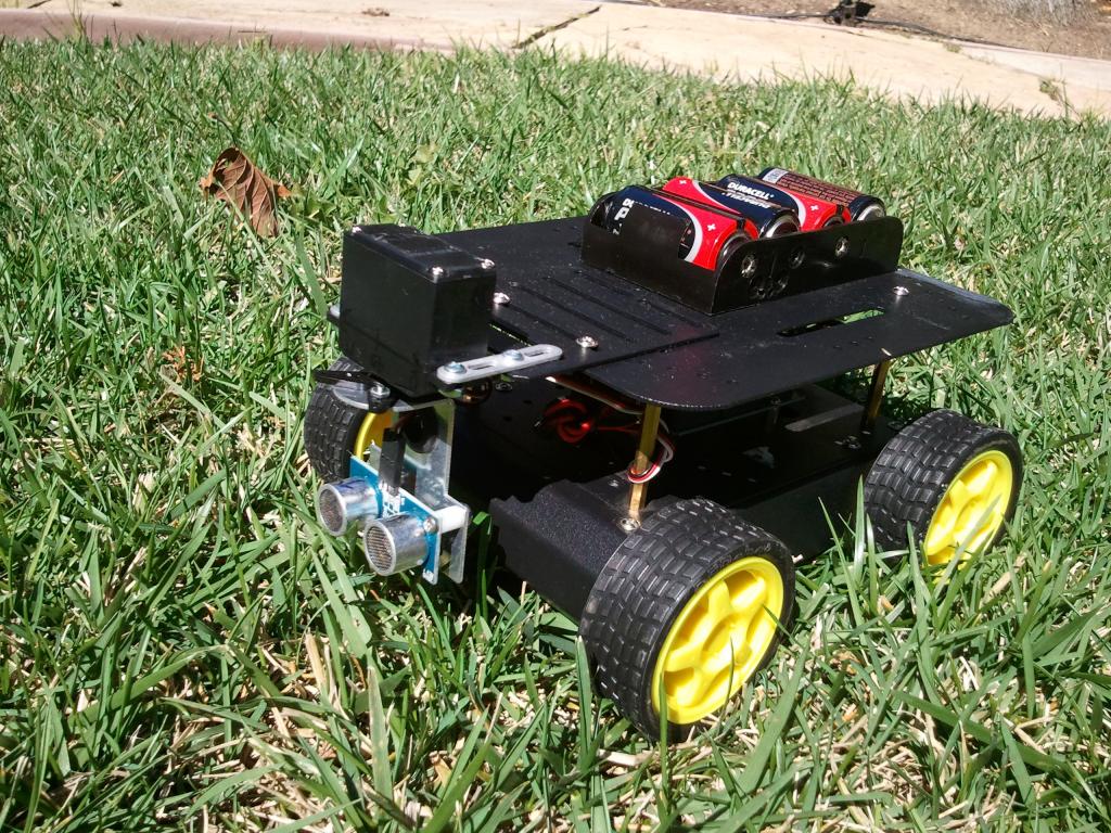
With regards to four wheel drive robots, they are best if the pair of wheels are closely spaced. In effect they act just like a normal differential steering robot. The book "Robot Builder's Bonanza" has a few pages on them and I used that design for the robot in this video.
That robot uses a BS2e and is compatible with unmodified Boe bot programs.Here are some images showing construction details:
http://www.ebay.com/itm/330801837993
If you can get both for $75, that would be a smoking deal. Ken or Matt will get you a new set of rubber bands for the wheels!
You could probably flip the BoE and get most of your money back. Wheel & deal !
I have a serial over blue tooh module on hand there cheap work at a decent distance to test things, and arent anymore difficult than using any other serial device, these can be purchased for 6 bucks. I know nothing about xbee or 433mhz tranciver type gear so BT should be suffiecent for now and is sitting here already used in other projects
Ive perty much bread boarded a 555 pwm just need to add an h-bridge, and a way to amplify the PWM signal
As far SAR radar goes I dont think ill have that working for a while and the purpose of it is not to use as a ping sensor, A scaled down version of the radar using the signal data can be used that way and I may do that but my goal is to collect the sar data and send it to my pc with a 3g connection so I can render the bots radar on my PC, kinda like sending a rover in to do radar sweeps of an area and let me know whats going on there. In noooo way do I think this system is going to be working in less than a year.
As far as cash being tight you have no idea, I have one 180 servo and a bunch of motors and gears to work with so thats probably gonna have to do for now as far as the drive train goes, Id like to build a feedback controller for the motors at some point too but thats way down the road!
Right now I want something rolling I can send serial over Bluetooth too control, then work on adding sensors and having it send the data back, then getting it rolling on its own. Im guessing this will be about 6 months before its autonomous at all... Right now im more concerned with building a working chassis with what I have and can get. I dont know much about motors or gears im reading though. If it doesnt work ill at least have a platform built which I can then figure out the drive train for when I can get some better motor stuff.
I have 2 matching kinda week motors I could do a 3 wheel differential drive bot with but im thinking ill have to use the drill motor to power an axel for two wheels and a servo to steer the front, its not a great setup but well see
I do tons of research and I know my first attempt will suck but i also know ill learn from it and do something better the next time, if i used a boe bot id still have no idea how to build a hardware motor controller. I also dont reach so high I cant accomplish stuff, the only part of this project I feel will pose any challenge is the acuall mechanical stuff and the SAR which im otally in agreement its fairly grandiouse but I just picked up a bunch of older analog design and microwave design books, hopefully ill be able to build one then scale it down from a sar to a long range ping a u controller can interpret. If I get that far though might as well through an Rpi on there and a webcam so I can do awesome machine vision and image the sar data to send it back via 3g.
This is totally a side side project too. If this thing can wake up based on an rtc and chase my dog half assly while doing something goofy with an emic or something within the next 4 months ill be happy. I chose to do a bot becuase it will give me alot of experince intergrating tons of different systems that just sticking to home brew pc stuff wont. I really dont see the need to build a bot other than that and maybe roll a SAR for me, if it could do dishes that be one thing
tottaly off but can anyone tell me the major advantage of a ping vs ir triangulation for short distant object detection? I have alot of IR stuff laying around maybe I could mimick a sharp IR range detector with, since I cant afford a ping even