Circuit Questions
I have three circuit questions to ask:
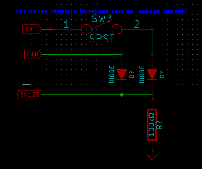
1. In the following circuit, should I have series resistors in line with each of the diodes? The specs are:
--- Batt is 0 to 4.5 volts
--- P10 is 0 or 3.3 volts (Propeller I/O)
--- EN123 is a digtal input, logic low of 0 to 0.4v, logic high of 1.2v to 6v, and leakage current of +-1uA
I want to have EN123 be high if either P10 or SW is asserted. So, this is similar to the logical "OR" condition.

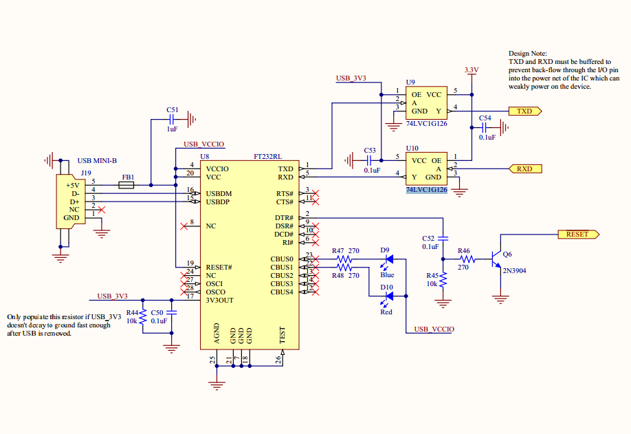
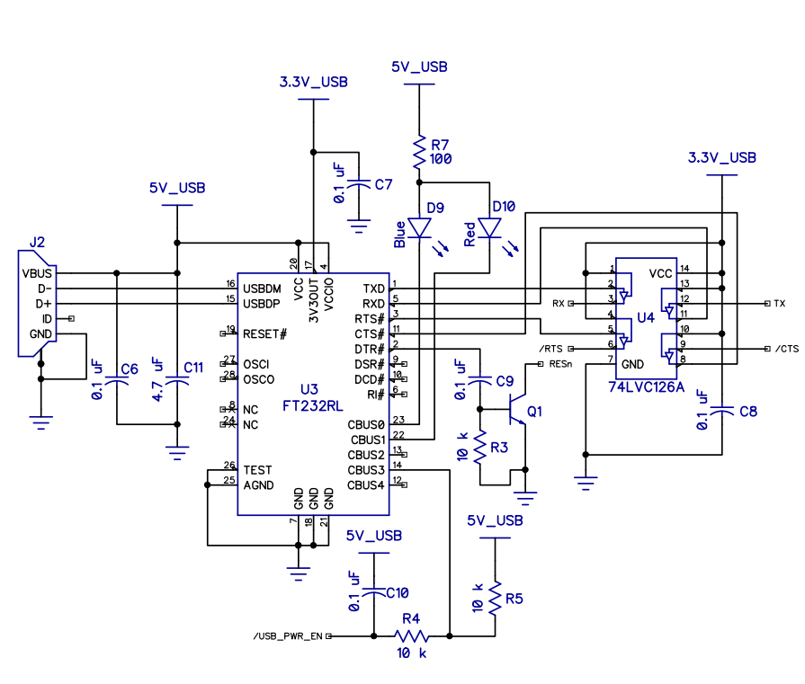
2. In the Quickstart reference circuit both the blue and the red LEDs are powered through the same 100Ohm resistor. From what I've learned, each LED must have it's own resistor. Does the Quickstart schematic have a flaw? For comparison, the Eddie control board (newer?) has a 270Ohm resistor for each LED.
3. How can I have two sources connected to the BOEn of the Propeller chip, and allow either (or both) to reset the Propeller?
--- Source 1: FTDI chip, standard circuit (see the circuits above).
--- Source 2: Logic 0 or 3.3v (pulled up, similar to I2C).
1. In the following circuit, should I have series resistors in line with each of the diodes? The specs are:
--- Batt is 0 to 4.5 volts
--- P10 is 0 or 3.3 volts (Propeller I/O)
--- EN123 is a digtal input, logic low of 0 to 0.4v, logic high of 1.2v to 6v, and leakage current of +-1uA
I want to have EN123 be high if either P10 or SW is asserted. So, this is similar to the logical "OR" condition.
2. In the Quickstart reference circuit both the blue and the red LEDs are powered through the same 100Ohm resistor. From what I've learned, each LED must have it's own resistor. Does the Quickstart schematic have a flaw? For comparison, the Eddie control board (newer?) has a 270Ohm resistor for each LED.
3. How can I have two sources connected to the BOEn of the Propeller chip, and allow either (or both) to reset the Propeller?
--- Source 1: FTDI chip, standard circuit (see the circuits above).
--- Source 2: Logic 0 or 3.3v (pulled up, similar to I2C).


Comments
edit: as Kwinn pointed out in #6 but I failed to mention, the LEDs must have a similar voltage drop for one resistor to work.
That was my attempt to indicate "anything". For practical purposes, let's say 6volts (more than battery or Propeller IO).
Does the EN123 input have built-in Pull-up resistor? (that is pretty common)
ORering is best done with open-drain layout, the Prop pin can be turned to an input to emulate that.
sharing a 100ohm, maybe the blue and red LED is never on at the same time? then is is perfectly OK.
2 Depends. If both diodes do not need to be on at the same time it is ok. If both are on at the same time the red one will be on due to it's lower forward voltage. So it really depends on what is needed.
3 A signal diode on each source with the anodes connected to BOEn.
-- I put the diodes in to prevent back current flow from one source to another. They are not LED.
-- The datasheet for EN123 says "Logic Input Pulldown Resistance" of 400-1200kOhms
-- Can you provide a schematic or a description of how it's connected? I'm unfamiliar with most EE concepts, and the internet isn't a help here.
-- I don't know. Does the FTDI do that? I wonder...
My main concern with question 1) is how to prevent the 4.5v of the battery from going back into the Prop, and vice versa.
If it does have ~800k Ohm pull-down,
it's very weak pull-down and is there just in case the mcu pin boot up as a input-pin and the voltage will not slowly creep up to a logic high.
Do you want the signal to pin EN123 on/high most of the time? or is low (gnd) 90% of the time?
And device could actually have active-low enable, so until I know ic name.
Designing a good pull-up/down layout is more of a consern when running on battery.
For item 3, you may need a zener ckt to limit the voltage out of the diode summing point. Then (no prop doc on hand) put that signal into the reset pin or via inverter if it should be /reset. Just quock thoughts.
EN123 is the name of the input pin on the device.
EN123 is high most of the time (active high), and yes: the system is running on battery.
With the internal 800k pulldown, you will create a 3/4 voltage divider.
But P10 should be output + high for on and turned to a input for off, as to not 1/2 volt divide the push down button.
Or you could use a 20k ohm for the button and it still will "win" e.g result is higer than 1.2v
Though a 800k is pretty weak, the good part is the extra 200k Ohm will reduse the battery drain a little more
And you should not use the 100k pulldown you have in the picture.