

Problems with the 74HC595 and 74HC165
 jcolonias
Posts: 31
jcolonias
Posts: 31
Hi,
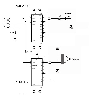
I am trying to utilize the expander circuit shown the Stampworks (p.143) which is a combination of a
74HC595 and a 74HC165. I intend to use it as shown in the attached picture, but for purposes of learning how it works; I use only one IR circuit.
The circuit is simple enough to wire on my Parallax professional board; therefore, I feel that the errors that I get are my programming which is also attached.
The programming is also the example given at Stampworks, plus the additional programming needed to
address the one input IR detector and the one output t IR Led.
Why do I get some times all ones, or all zeros in the DEBUG statement, and my IR test in the program never works!
I hope it is something I do not understand in the way the expanders work, and I would appreciate very much if any of you could help me to overcome this problem and go ahead in implementing the circuit with more IRs.
Thanks, John
374 x 420 - 36K
bs2
3K
Comments
The I/O expanders make it easy to add Input/Output pins to your BASIC Stamp Microcontroller, however the inputs/outputs cannot take on the special functions available to the pins on the BASIC Stamp Module itself. For IR detection the BASIC Stamp Module generates a 38.5kHz pulse on the output pin to the IR LED. The IR detector is designed to operate and decode data at that frequency, however it is not possible in this configuration to generate the 38.5kHz you're expecting.
I/O expanders on the BASIC Stamp Microcontroller are better suited to high/low input/output functions such as controlling LEDs or drivers for relays. Likewise the inputs are great for scanning large numbers of buttons or DIP switches. However you have to remember that it takes time to shift the data out and then latch it to the pin in the case of the 74HC595 and time to latch and shift in the data from the 74HC165. You would need a high-spped microcontroller to do this in that manner using shift registers. If you have further questions please reply and I will do my best to help.
Thank you so much for clearing this point! I was sure that there was something that I did not understand
about the function of these chips, and your comments made everything clear.
Now I got to think of another way to run 4 IRs. Maybe I can use two BS2 (since I have about 5 of them)
and put 2 IRs on each BS2.
Would that work?
Thanks again,
John
The sensors would have to be separate, on separate I/O pins. If you'd only use one sensor at a time, you could use a multiplexor like this one.
Thanks for the suggestion. I will try it.
John
If you're just trying to save I/O pins then use the pins on the BS2 to handle the IR stuff directly, that will consume several I/O pins, but you can still use shift registers to offload output only and/or input only high/low functions to devices that don't need to use special commands and will always just be a 0 or 1. You have to use the pins on the BS2 when you're using commands like FREQOUT, PULSIN, PULSOUT, RCTIME, SERIN, SEROUT, etc. Basically any command that does anything but read an input high/low or send one out. If you have several of those that's when the shift registers really become useful. Driving an array of LEDs, relays, etc. I hope this helps.
im have a projetc with hc595, but my problem is a noise in circuit.
Some times the number changes. Ex:
I send: 11001100
and the result is: 11011100.
Can you help me?
Rodrigo Ribas