Problem connecting to Micro SD Card on a Adafruit Micro SD Breakout Board
 Akkarin
Posts: 43
Hi,
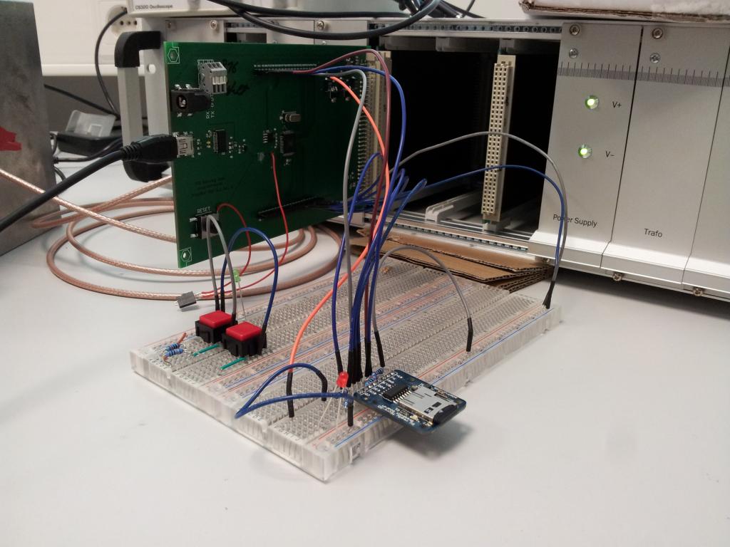
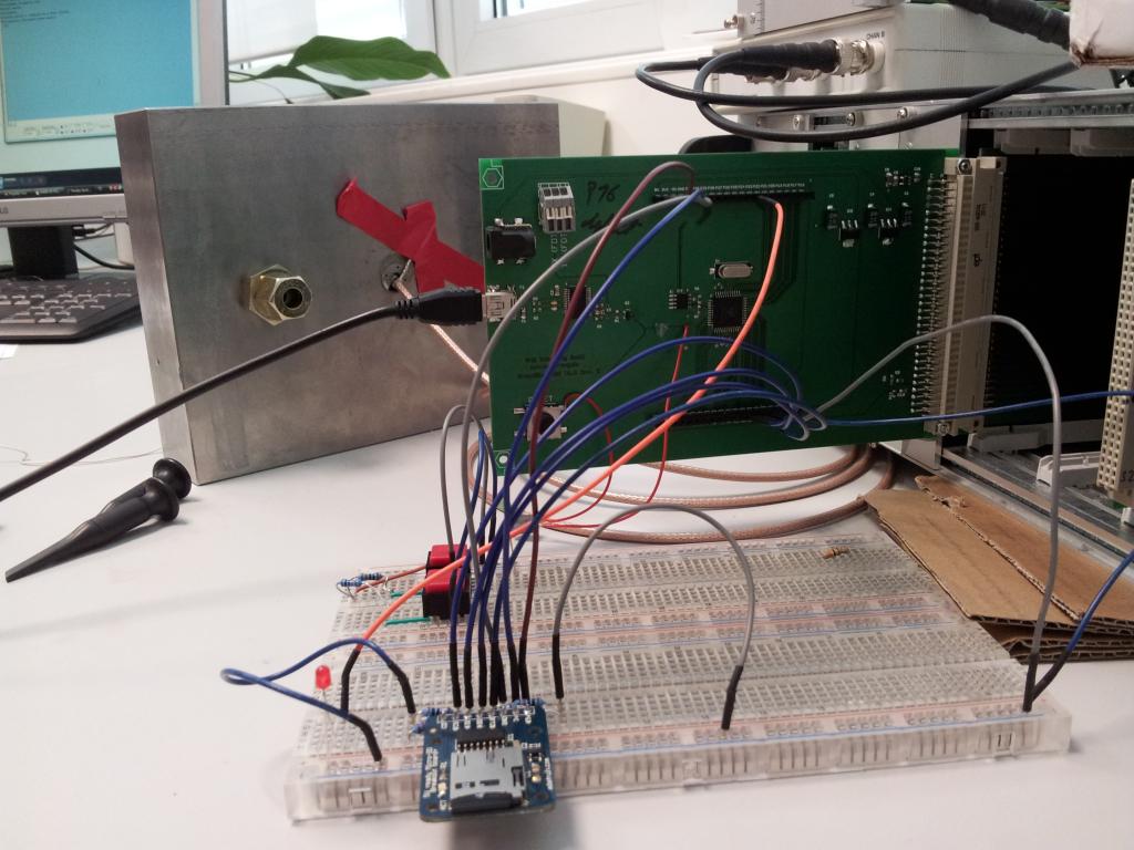
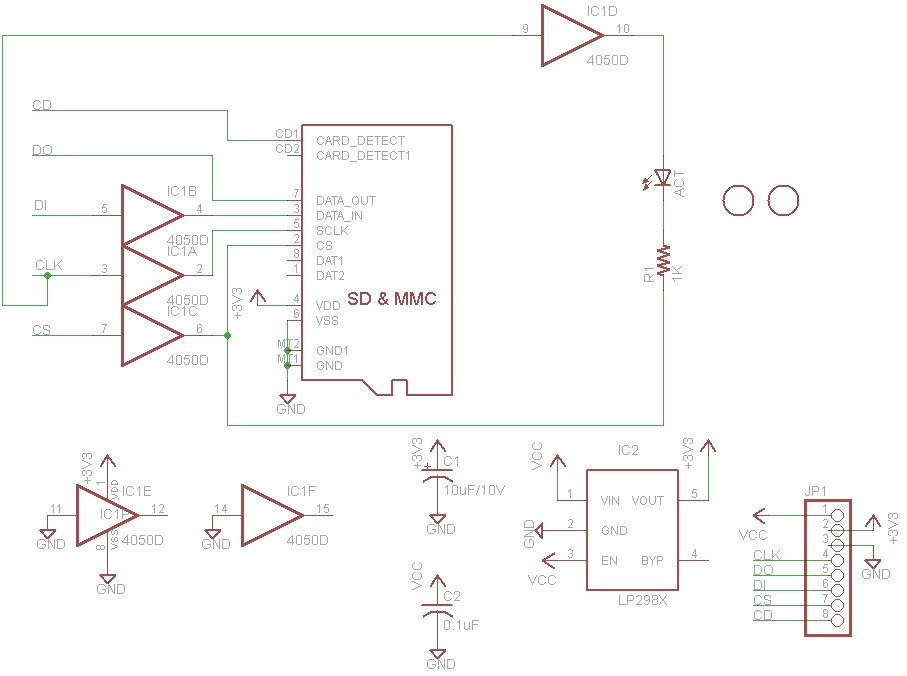
I'm trying to connect a micro SD card to the Prop by using a Breakout Board from Adafruit (schematic attached) on a breadboard, see photos.
On the first try I wanted to use Kye's Full File System Driver without RTC version:
// Author: Kwabena W. Agyeman
// Updated: 8/31/2011
// Designed For: P8X32A
// Version: 2.0 - Special.
I loaded the provided !SD_card_profiler and changed the pin numbers accordingly (I hope). I guess that _doPin must be connected to the SD card's DO Pin and not DI, right? I mean it's not like Tx and Rx on serial devices where you connect Tx from the transmitter to Rx on the receiver, right? I also use 10k pullups on all lines, see photos. You think the jumper wires are too long or pickup interference?
The only thing I get is the statusLED blinking at 1Hz, which means that something went wrong. I tried to get the errorcode by printing the errorstring on the PST like so:
On terminal I see 3872, does that mean I get errors 3, 8, 7 and 2? Because to my understanding there is no error 3872, right? Or do I have to convert errorstring in some way? <- see EDIT.
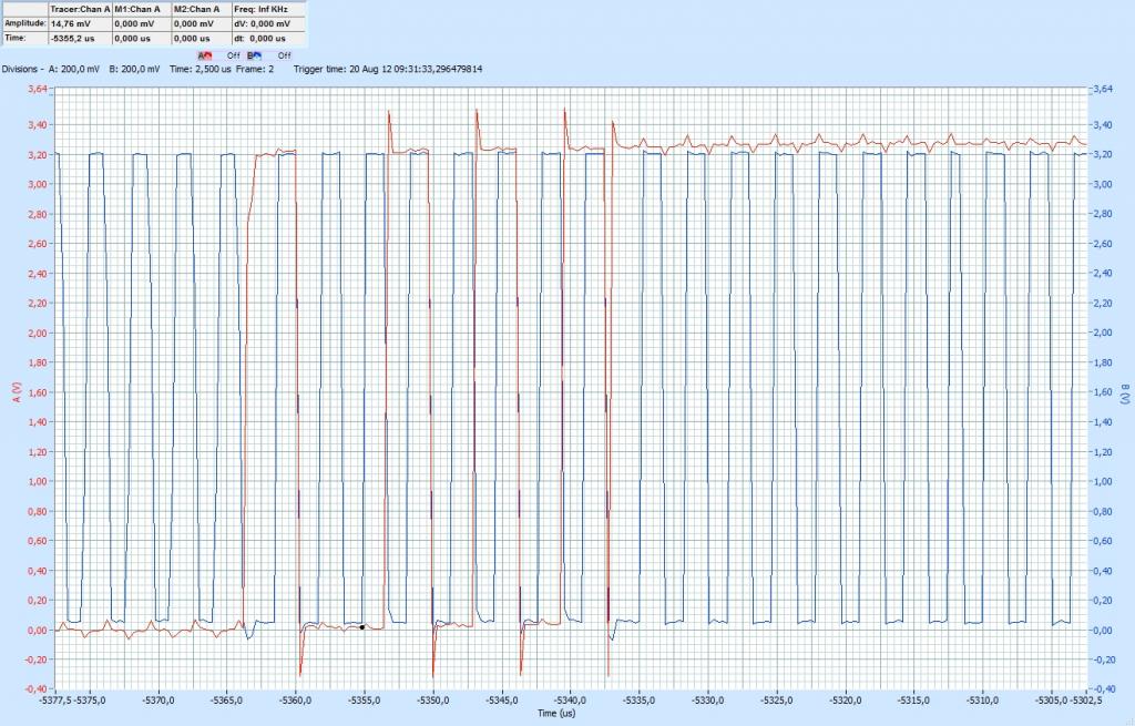
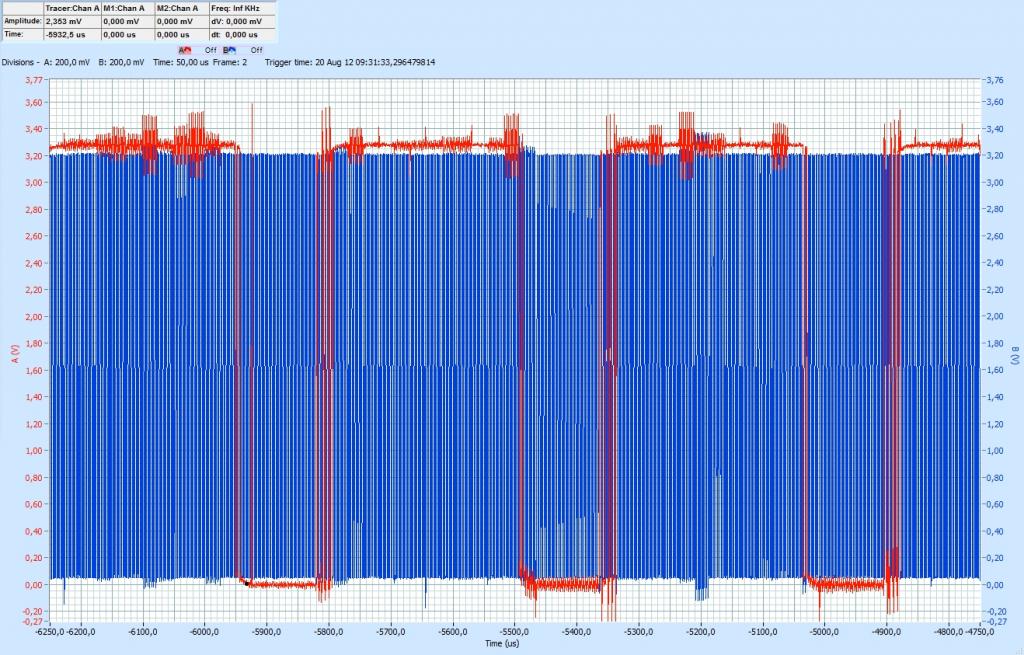
I also attached some waveforms from the CLK and DI lines. To me, that looks OK. I mean it's not perfect since I get interference in the DI line every time CLK toggles but it should work. I probed on the breadboard as close as possible to the µSD card.
Ok, since I think my wiring is correct and the pin numbers are too, it's time to think about µSD itself. First I tried a brandnew Sandisk 16GB class 10 SDHC. I formatted it using the Windows onboard formatter to FAT with 32kB blocks. I confirmed that I can write and read from the card on 2 different PCs. So the card should be OK.
Then I tried another, older, card: 4GB class 4 SDHC (Sandisk). First I formatted the same as the other card and then I even used the SD Formatter 3.1 from SDA: https://www.sdcard.org/downloads/formatter_3/
But of course: no success
I also tried fsrw26 with the provided test.spin but it doesn't work either. Of course I changed the pin numbers in "sysdep".
First and second mount succed but reading block 0 fails with error -100, which should be "ERR_ASM_NO_READ_TOKEN". Well, what does that mean?
Ok, any ideas? Help would be gladly appreciated
- Akkarin
EDIT: Ok, I see that my approach to get the errorcode in Kye's Driver was wrong. I now used errornumber := fat0.partitionError which gives me an errornumber of 1 which is "Disk_IO_Error". That makes sense.
I'm trying to connect a micro SD card to the Prop by using a Breakout Board from Adafruit (schematic attached) on a breadboard, see photos.
On the first try I wanted to use Kye's Full File System Driver without RTC version:
// Author: Kwabena W. Agyeman
// Updated: 8/31/2011
// Designed For: P8X32A
// Version: 2.0 - Special.
I loaded the provided !SD_card_profiler and changed the pin numbers accordingly (I hope). I guess that _doPin must be connected to the SD card's DO Pin and not DI, right? I mean it's not like Tx and Rx on serial devices where you connect Tx from the transmitter to Rx on the receiver, right? I also use 10k pullups on all lines, see photos. You think the jumper wires are too long or pickup interference?
The only thing I get is the statusLED blinking at 1Hz, which means that something went wrong. I tried to get the errorcode by printing the errorstring on the PST like so:
CON

  _clkmode = xtal1 + pll16x ' The clkfreq is 80MHz.
  _xinfreq = 5_000_000 ' Demo board compatible.

  _dopin = 14
  _clkpin = 15
  _dipin = 13
  _cspin = 12
  _cdpin = -1 ' -1 if unused.
  _wppin = -1 ' -1 if unused.

  _rtcres1 = -1 ' -1 always.
  _rtcres2 = -1 ' -1 always.
  _rtcres3 = -1 ' -1 always.

  _statuspin = 23 ' Status LED pin number.

OBJ

  fat0: "SD-MMC_FATEngine.spin"
  fat1: "SD-MMC_FATEngine.spin"
  pst : "Parallax Serial Terminal"

PUB main | errorString
  pst.start(115200)
  ' "fatEngineStart" is only called once. Either driver object can call it.
  fat0.fatEngineStart( _dopin, _clkpin, _dipin, _cspin, _wppin, _cdpin, {
                    } _rtcres1, _rtcres2, _rtcres3)

  statusLED(4) ' Make the status LED blink quickly.
  errorString := \profiler ' Returns the address of the error string or null.
[B]  pst.dec(errorstring)[/B]
  pst.newline
  if(fat0.partitionMounted)
    \fat0.unmountPartition
  if(fat1.partitionMounted)
    \fat1.unmountPartition

  if(errorString)
    statusLED(1) ' Blink the LED if an error occurs.
  else
    statusLED(-1) ' Light the LED if no error occurred.

  waitcnt(clkfreq + cnt)
  fat0.fatEngineStop ' Give the block driver a second to finish up.

  repeat ' Wait until reset or power down.
On terminal I see 3872, does that mean I get errors 3, 8, 7 and 2? Because to my understanding there is no error 3872, right? Or do I have to convert errorstring in some way? <- see EDIT.
I also attached some waveforms from the CLK and DI lines. To me, that looks OK. I mean it's not perfect since I get interference in the DI line every time CLK toggles but it should work. I probed on the breadboard as close as possible to the µSD card.
Ok, since I think my wiring is correct and the pin numbers are too, it's time to think about µSD itself. First I tried a brandnew Sandisk 16GB class 10 SDHC. I formatted it using the Windows onboard formatter to FAT with 32kB blocks. I confirmed that I can write and read from the card on 2 different PCs. So the card should be OK.
Then I tried another, older, card: 4GB class 4 SDHC (Sandisk). First I formatted the same as the other card and then I even used the SD Formatter 3.1 from SDA: https://www.sdcard.org/downloads/formatter_3/
But of course: no success
I also tried fsrw26 with the provided test.spin but it doesn't work either. Of course I changed the pin numbers in "sysdep".
First and second mount succed but reading block 0 fails with error -100, which should be "ERR_ASM_NO_READ_TOKEN". Well, what does that mean?
Ok, any ideas? Help would be gladly appreciated
- Akkarin
EDIT: Ok, I see that my approach to get the errorcode in Kye's Driver was wrong. I now used errornumber := fat0.partitionError which gives me an errornumber of 1 which is "Disk_IO_Error". That makes sense.


Comments
ARE you providing both 3.3v and 5v to the sd breakout board?
It looks like you are, so really to fix your problem, just pull one of them out and thats it.
By the schematic, it shows that if you provide 3.3v, you don't need to supply 5v.
If you are providing both, this might be your problem. Choose just one.
If you have a 3.3v regulator on that main PCB, and you are allowing the adafruit breakout to also regulate 5v down to 3.3, depending on which regulator is better at its job, one will be supplying the others circutry with power, this will cause odd power movement in your wiring (i.e. 3.3v jumper wire could actually be moving current backwards into the pcb device)
I read over ladyada's writeup on this breakout board, and she dosen't mention this at all, which is kinda important.
http://www.ladyada.net/products/microsd/#what_to_watch_for
Having 2 DIFFERENT voltage regulators in parallel, is not a good idea.
Note how she DOESN'T have the 3.3v line connected in her example here.
http://www.ladyada.net/images/microsd/microsdwiring.jpg
But thats because her arduino is 5v only.
In your case you are providing 3.3v because you already have it on your pcb.
But its up to you, provide ONLY ONE supply input.
When working with breadboards and jumper wires, I found in my testing of 55 propeller chips, that ALL jumper wires, power, ground, clock, di, do, etc SHOULD be the exact same length, and attach to the breadboard near each other.
The total length of the wires is probably less of a concern if ALL wires are the same length.
(if pulling one of the supplies to the card dosen't fix the problem, shorter wires, like ladyada says, might be the fix)
But in that picture, every wire is of different length, they all connect to the breadboard at different locations(not near sd card).
The wires are also in a fairly messy state (not sure if it matters tho, you could try to twisty tie the bundle (of same length wires) together.
thanks for your answer. Yes, when I took the picture both 3V3 and 5V where connected but I was desperate then already and just gave it a try. Normally I connect only one supply, either 5V or 3V3 which come from LDO regualtors on the Prop PCB, no resistor divider or something.
Actually all lines from the Prop PCB to the breadboard are the same length, 200mm, although it might look different in the photo. Only 3V3 for the pullups are shorter and not exactly next to the µSD breakout board but all other lines (CS, DO, DI, CLK) connect to the breadboard and right next to the µSD breakout board.
Ignore the red pushbuttons in the background. They are not connected at all.
Perhaps add some more decoupling (100uF electrolytic) at the breadboard. What are all those resistors for?
The power, and data, should all be same length, connect to breadboard in same area, and like mark says, add some caps to that breadboard near the sd card, and bundle the wires with the ground.
Im not clear on your reply, did you try it with JUST one power supply input?
It seems like you are saying you tried this first, it didn't work, so you tried supplying both power input.
1. Most definitely only connect one power supply.
2. Throw a capacitor onto that breadboard. (this is probably the best thing to try first)
3. Bundle all wires with the ground.
I reckon you refer to the two lines in the right hand corner (the long grey and blue)? They only supply GND and 3V3 for the status LED and pullups. The 5V or 3V3 for the breakout board come from the Prop PCB directly. And they all are 200mm, really. Only exceptions are the short blue and grey which connect the pullups to that 3V3 rail.
That's right. This double connection was a one time shot and unfortunately I took the picture just then. Before that I tried 3V3 OR 5V.
Anyway, I exchanged all the wires to 100mm long ones and soldered a 100µ cap in, although there is already a 10µF on the breakoutboard itself. See photos. But still no luck
thanks for the hint. I tried this before by changing the pin numbers in I/O driver (this should be as good as physically reconnect the wires, right?). Now I tried it again and: now the status LED blinks quickly like 4 times and then starts to blink at 1Hz. Is this a good or bad sign? I mean Kye states in his driver that _doPin should be connected to pin 7 of the µSD Card, which it was before changing Di and DO, but then the status LED doesn't blink quickly at all, it just starts blinking at 1 Hz.
I already thought that I might have damaged the µSD Card, but both of them still work fine with my PC.
The 1 Hz blink rate means failure. It says that at the top of the code. Blinking quickly means it's working.
Also, the SD card may just not work with the driver. Try another one.
Thanks,
error code is 1 (Disk IO error).
I only have two cards available, both SanDisk, see first post.
I have to try more tomorrow.
Thanks to all so far
it's working now. But not with the Adafruit breakout board
Either it is broken or I don't understand how to connect it properly.
Anyway, I soldered some pinheaders on my micro SD to SD Adapter, see photos. After I found out, that the pin numbering shown on the german Wikipedia is not correct or at least misleading, I connected the adapter as shon on this site. Yeah, success. I mean the pic from Wiki suggests that e.g. pin 3 of the SD is connected to pin 3 of the µSD, which it is not since on the SD card pin 3 is GND and on the µSD it is DI, right?
I'd really like to know why Adafruits board doesn't work. Maybe I blew it up just at the beginning? But the signals looked OK on the oscilloscope, even at the outputs of that level shifter IC.
Well, I'm glad I got it working somehow. BTW, it's working with both, Kye's Full File System and fsrw26.
- Akkarin