

Designing a VGA DAC for the Propeller
 Mervin
Posts: 8
Mervin
Posts: 8
I want to do VGA generation on my propeller chip for one of my projects
and since I'm new to doing that kind of thing I'm having some trouble understanding some things.
I hope someone can help me out.
- I want to use 5 bits for each color channel (RGB15)
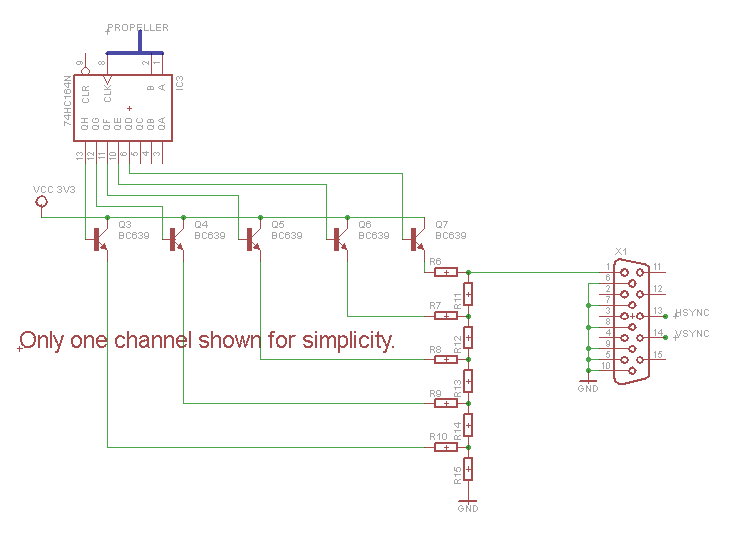
- The setup which I would like to use is: Propeller --> 2x 8bit shift register --> Transistors --> R2R Ladder --> VGA Port (640x480 @ 30 Hz or lower if possible, 60 would be overkill)
I've looked at some examples and I've tested some things in simulation software but I can't quite figure out which resistor values to use for the R2R ladder to get a 5bit range at vcc 3.3v from 0v to 0.7v
Some examples seem to conflict with eachother even.
Sources I used:
http://www.avr-asm-tutorial.net/avr_en/AVR_DAC.html
http://www.brischalle.de/JDAC/DAC_R2R_network_calculation_en.html
My circuit:
and since I'm new to doing that kind of thing I'm having some trouble understanding some things.
I hope someone can help me out.
- I want to use 5 bits for each color channel (RGB15)
- The setup which I would like to use is: Propeller --> 2x 8bit shift register --> Transistors --> R2R Ladder --> VGA Port (640x480 @ 30 Hz or lower if possible, 60 would be overkill)
I've looked at some examples and I've tested some things in simulation software but I can't quite figure out which resistor values to use for the R2R ladder to get a 5bit range at vcc 3.3v from 0v to 0.7v
Some examples seem to conflict with eachother even.
Sources I used:
http://www.avr-asm-tutorial.net/avr_en/AVR_DAC.html
http://www.brischalle.de/JDAC/DAC_R2R_network_calculation_en.html
My circuit:

737 x 535 - 21K
Comments
Firstly a big Hello and Welcome.
Please have a look at this thread were I run through the calculations for a 6 bit DAC out of the prop, for Greyscale operation
http://forums.parallax.com/showthread.php?131622-Resistor-values-for-64-GreyScale-VGA-output-from-the-Propeller
Towards the bottom of the thread Lawson uses R2R networks - 91 ohms and 160 ohms are suggested because the 27 ohm driving resistance of the prop pin drivers.
What kind of resolution are you hoping to achieve? Remember the hub ram (where the video buffer is) is 32kB, and you need to leave some space for your program.
I'm reading your thread on my other monitor as I'm typing this:
I'm hoping to achieve a resolution of 640x480 @ at least 24hz with 5 bits resolution per color channel. (RRRRRGGGGGBBBBB) colors will be stored in several 256 color palettes in the main RAM and the framebuffer will be stored in an external RAM chip.
Thanks for the information and the formulas I'm sure this will get me going
With evertyhing under consideration and with the number of free pins which I have left shrinking rapidly I have chosen to use the RRGGBBII palette with 2 video modes available: 256x240@24Hz and 480x270@30Hz
I have designed the following R2R DAC (repeat for each color channel):
(the 27 Ohm resistors and switches represent the Propeller outputs)
I'm still having a lot of trouble figuring out how to control the 2 intensity bits of all 3 channels (R,G,B) at the same time from 2 propeller pins,
I would love to get some info on how to tackle that problem.
There's some good stuff in this thread..
http://forums.parallax.com/showthread.php?140426-VGA-using-8-bits-RRGGBBII-HS-amp-VS-10-pins-Discussion....
edit:
and here:-
http://forums.parallax.com/showthread.php?141143-VGA-256-Colors
-Phil
With your simulations don't forget to terminate the outputs via a 75 ohms resistor to simulate the monitor load to make them give you your 0.7v peak.