

Another sine-wave output technique
 Phil Pilgrim (PhiPi)
Posts: 23,514
Phil Pilgrim (PhiPi)
Posts: 23,514
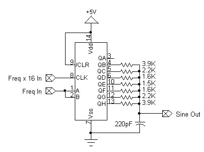
In my continuing quest for fast sine-wave generation on the Prop, I came across this technique (see reply #10), which I've reproduced with a slight modification. The IC is a 74HCT164 SIPO shift register. A 74VHC164 would be a better choice, since it can reach higher frequencies, but I didn't have one.

Rather than configuring the shift register as a Johnson counter and introducing a logic delay with an inverter, I'm using a separate Prop pin to emulate what the inverted output would be. This has to be done carefully, though, in order to maintain the proper phase relationship between the signal shifted in and the shift clock. That's the reason for using the inverted output from ctra in the following program:
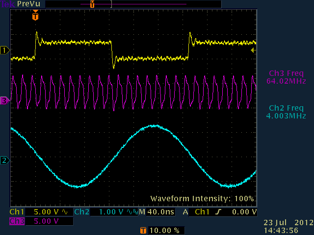
Here's what the output looks like for a 4 MHz clock:

Note that this technique does not eliminate or reduce phase jitter. This is because the 16x shift clock period is much longer than the jitter's phase variation. To reduce jitter in a DDS situation, the sine-weighted DAC granularity has to be much smaller than the jitter amount. Since that standard is nowhere close to being met here, I consider this to be just a footnote in my continued quest.
-Phil
Rather than configuring the shift register as a Johnson counter and introducing a logic delay with an inverter, I'm using a separate Prop pin to emulate what the inverted output would be. This has to be done carefully, though, in order to maintain the proper phase relationship between the signal shifted in and the shift clock. That's the reason for using the inverted output from ctra in the following program:
CON

  _clkmode      = xtal1 + pll16x
  _xinfreq      = 5_000_000

  PLL_PIN       = 0
  NCO_PIN       = 1

  FREQ          = 4_000_000

PUB  start

  frq0 := frqval(FREQ)
  cognew(@sine, 0)

PRI frqval(a) : f     'Thanks, Tracy!

  repeat 32
     a <<= 1
     f <<= 1
     if a => clkfreq
        a -= clkfreq
        f++

DAT

sine          mov       frqa,frq0
              mov       frqb,frq0
              shl       phsb,#2
              mov       ctra,ctra0
              mov       ctrb,ctrb0
              mov       dira,dira0
              jmp       #$

frq0          long      0-0
ctra0         long      %00011 << 26 | %111 << 23 | PLL_PIN << 9 | 31
ctrb0         long      %00010 << 26 | %011 << 23 | NCO_PIN
dira0         long      1 << PLL_PIN | 1 << NCO_PIN
Here's what the output looks like for a 4 MHz clock:
Note that this technique does not eliminate or reduce phase jitter. This is because the 16x shift clock period is much longer than the jitter's phase variation. To reduce jitter in a DDS situation, the sine-weighted DAC granularity has to be much smaller than the jitter amount. Since that standard is nowhere close to being met here, I consider this to be just a footnote in my continued quest.
-Phil
420 x 313 - 4K
640 x 480 - 16K
Comments
On a prop you gain 8 'dots' in the Y axis that you can update at up to 25ns step rates, so you are ahead of a Pin-DAC, but not by a lot. You are a little further ahead of a software update rate, but are stuck with 8 dots in Y and f/16 in X ...
This is unlikely to be ahead of a Video Generator DAC tho ?
What would be nice, would be some means to interpolate those X,Y values, as the clock lowers...
Not sure there is any 'easy' way to do that ? - it would also need a third timer output, so bumps above 1 COG ?
I guess you could couple this with a COG-Table, and use a Tristate Shift register, so either the SR or the Prop drives the DAC.
At highest speeds, the SR delivers the sine, and at low speeds you could fit up to 1024x in Table, and dither in Y to go above 8 levels, but I'm not sure how the skipping action of an adder would 'beat' with the picket nature of the dither components.
Probably 'not well'.
Of course, this may all be mooted by the Prop II, which will have sine-wave DAC output built in. It remains to be seen, however, what the jitter component will be, since all its outputs have to be synchronized to the system clock, rather than free-wheeling PLL-style, as in done in the Prop I.
-Phil
Perhaps another idea could be to use the video generator to output on 2 pins. Of course the cog would be used to keep the waitvid supplied.
-Phil