

Joystick Assistance Appreciated
 BrainStrain
Posts: 30
BrainStrain
Posts: 30
Hello everyone!
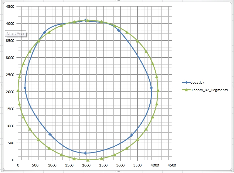
I am building a robotic wheel chair and I have just gotten a Propeller Proto board to run a Parallax joystick; part number 27800. I've plotted a range of eight coordinates the joystick produced and displayed in the Propeller Tool's terminal window. The joystick X Y coordinates mapped to something close to a circle in Excel. I then plotted a perfect circle around my test data to see the difference between my test results and the joystick's maximum range, based on a 4,096 point diameter. I have included my graph, below. The LTC1298 analog to digital converter the joy stick was running through produced data from 0 to 4,095. I want to express my huge thanks to Chip Gracey for writing the Spin code for the joystick! It saved me an enormous amount of time.
Now I figure the next step is to get the joystick's movement to light up some LEDs to represent directions of travel. I'm a newbie so this is deep water. I worked with an Arduino platform enough to get it to accelerate and decelerate a motor while LEDs indicated the state of acceleration, deceleration, and the stopped state. Then my attention turned to the Propeller chip.
I'm still a stone-cold rookie, so I need some help on how to approach working with the joystick. As a side note, I've written a half-dozen modest Bash scripts in my life and I've spent most of the last 15 years doing computer forensics, but I've had no training in programming... and I know very little about electronics - an unfortunate state of affairs.
I think the next step is to get the Propeller chip to read the X Y values coming from the joystick, average them every-so-many milliseconds and then compare them to a table of known (plotted) values in order to select the closest known value. The closest value would then be used to light the appropriate LED. I think a good way to approach the need to plot joystick points in addition to those on the perimeter is to define a series of concentric circles within the joystick's range. The additional known points could be used to run the LEDs from dim to bright, and eventually be used to accelerate and decelerate the wheel chair's motors.
The catch is that I don't know how to do any of this. I've been reading Programming The Propeller with Spin - A Beginner's Guide to Parallel Processing, and the Propeller Education Kit Labs: Fundamentals. With your help I hope I can get my project running in months rather than years.
Expertise and general suggestions will be greatly appreciated.
BrainStrain

755 x 558 - 243K
Comments
You can use one of several different algorithms for this task.
Here's one I use in my Propeller BOE-Bot.
wheelSpeed[_PortWheel] := (channel[_Y] - channel[_X]) + _StopServo
    wheelSpeed[_StarboardWheel] := _StopServo - (channel[_Y] + channel[_X])
The above algorithm assumes the x and y values are zero when the joystick is centered.
For onmi-wheel drives you can use use the floating point arctan2 method to calculate the direction the joystick is deflected to control the robot direction of travel and also find the distance from the center point to control the robot's speed.
I'm sure an algorithm could be used to light the LEDs as well.
Normal hobby servos are refreshed 50 times a second. This is fast enough to appear to be realtime. I don't think you'd need to be able to update the speed of your motors faster than this.
Duane, It looks like you are a fellow who knows exactly what is needed. Thank you very much for the response.
I should probably divulge that my inspiration for this project came about a year ago. My cousin Jon's 17-year-old daughter, Chelsie Hill, got paralyzed from the waist down in a car crash in Feb 2010. She is now 20. About a year later I came to realize that nice motorized wheel chairs cost as much as automobiles. Jessica, the greeter at my local Home Depot, said her chair cost $25,000, and I can tell you, it is nice. I asked a woman who appeared to be in her 70s about her chair in front of the local Target store. The chair was not nice, not attractive at all, but it scooted down the street very well. It cost $16,000. It struck me that I could do better than that. Paraplegics need an inexpensive powered chair when insurance and Govt. programs won't pay for it. So over the last year I designed and built a prototype chair that Chelsie and I are pleased with. Now it is time to build chair prototype II with some of Chelsie's ideas built in. It is also time to start on the robotic wheel base. During the year of my chair build, Chelsie got a spot on a new reality TV show called Push Girls, on the Sundance Channel, Monday evenings at 10PM East coast time. Chelsie has not been in every episode, but you can see Chelsie at:
http://thesundancechannel.com
[Click over on the left of the Web page, where it says "Push Girls."
Getting back to technical stuff. Here is some more info:
Omni Wheels: Yes, that is exactly what I plan to use. I'm going to go with three 5", 250LB capacity wheels and three motors. I don't plan to use any servos. The motors will be controlled and coordinated with PWM, and position encoders. I might mention that there is a physical challenge of fitting encoders to motors that were not designed for them. And the wheel chair is going to be driven by a rider who can adjust joystick positions just like steering a car, in real time. If she drives over a pile of laundry or the wheels slip on a surface, perhaps human joystick steering can handle that as well as position encoders. I don't know the answer to that, being a rookie. The answer to using encoders is probably yes, because I might find out very quickly that steering without them would be much too sloppy.
Joystick X,Y Values: The Parallax joystick produced X1967, Y2112 coordinates as the "Centered" position in the LTC1298's 0-4096 range of output. That value can vary by a point or two on both axes. I plotted the perfect circle in my diagram with the center at X2048, Y2048, the center of a 4096 x 4096 circle. The forward position goes to the 4095 maximum of the available 4096 values, but Back only goes to 200, not zero.
Your advice to use the floating point arctan2 method to calculate joystick direction and also determine the distance from center sounds perfect. My research came across a couple of sources that said controlling omni wheels required some trigonometry, which I have not touched since I was a junior in high school... about 1968. No calculators back then, just a slide rule and function tables, the the school did have a paper-tape computer that we used once. It made punch cards look high tech.
Getting down to coding (and thank you for the code), it seems to me I need to:
1. Figure out what Spin code commands are going to accept as input the coordinates I am seeing in the terminal window.
2. Process the incoming X, Y data, whether through use of a table (which I would have to build) or by use of trigonometry. Let's call this task slicing and dicing the data.
3. Translate the sliced and diced data into directions of movement that I can use to activate defined movements for three motors, or turn on a circle of eight LEDs for starters.
Thank you again, Duane, for responding.
While on the hunt for such wheelchairs I have come across countless ones in very fine condition for just a few hundred dollars. Generally they will need a pair of proper deep cycle batteries - not car batteries like a lot of folks tend to use since they are so much cheaper.
A craigslist search for "electric wheelchair" returned these (and many others), all of them well under $1K.
http://seattle.craigslist.org/tac/hab/3129037836.html
http://seattle.craigslist.org/skc/hab/3142962824.html
http://seattle.craigslist.org/skc/for/3143460286.html
http://seattle.craigslist.org/sno/hab/3145695305.html
http://seattle.craigslist.org/oly/for/3154506209.html
http://seattle.craigslist.org/oly/for/3152209983.html
http://seattle.craigslist.org/sno/hab/3130207241.html
http://seattle.craigslist.org/see/had/3151140069.html
http://seattle.craigslist.org/est/mcy/3133628915.html
I'm very willing to help with the software if still want to build one yourself.
I know I have code to translate joystick positions to motor commands for a three wheeled omni bot. Here's a picture of a omni wheeled robot I made.
There are some more pictures here.
I'm not sure how important having encoders on your motors will be. Encoders are very important for an autonomous robot but humans are really good and compensating for speed differences in motors as they manually drive.
Another factor that could cause the need for encoders is if the motors are underpowered. For example my Mecanum wheeled robot was powered by motors smaller than ideal for the size of the wheels I was using. My robot performed much better once I added encoder feedback so the motors knew they needed more power for a target speed setting. Rich also built a robot with the same Mecanum wheels with much more powerful motors. His robot didn't have any trouble without encoders since they would just move as fast as Rich commanded them (with a RC remote).
You mentioned the difficulty of adding encoders to motors after the fact. One of my recent projects was to write software to read from some magnetic encoders. I've also been designing some curcuit boards for these encoders. I think there are some applications where these sensors would make it easier to add encoders to motors. I'm hoping to make a PCB small enough to fit where the potentiometer is located on a normal hobby servo so I can add position feedback to continuous rotation servos.
Are you planning on building your own omni wheels? I don't know of any omni wheels off the top of my head strong enough to use on a powered chair but that doesn't mean they don't exist.
I don't recall ever posting code for my three wheeled omni wheeled bot. I'm very willing to do so when/if you'd like to see it.
I'm going to have to play around with my future posts. I tried to get Chelsie's picture a little bit bigger, but I see Duane's picture is large... I'll have to figure it out.
Duane - YES! I am more than willing to accept your generous offer. And great work on your bot. Your wheels look very much like mine, except mine don't have the fancy centers. I might use drive hubs very much like yours. I bought a set of 5" omni wheels from Magnus down in southern California. They distribute for Rota Caster, the Australian inventers of the omni wheel, inspired from the Bibical story of Ezekiel's vision, a wheel within a wheel. My wheels are casters, not drive wheels. They are meant for hand trucks and have a load capacity of 250lbs each.
That's great about you guys having success without encoders. I plan to learn how to use them, but cost and simplicity are a priority. Good luck with your encoder work.
Yup, code and a bit of good explanation might get me powered up by the weekend.
Thanks
I'm not sure if the argorithm is the best for this kind of three wheeled omni wheeled setup. I wanted to try to write my own algorithm so I never searched to see if there's a better way of doing this.
Here's the main loop.
PUB mainLoop | indexPrivate
    repeat
      x := _Stop - pulseWidth[1] + 9
      y := pulseWidth[2] - _Stop - 6

      z := _Stop - pulseWidth[3]
      x *= 2
      y *= 2
      z *= 2

      fX := FMath.fFloat(x)
      fY := FMath.fFloat(y)
      fTargetSpeed := FMath.FSqr(FMath.fAdd(FMath.fMul(fX, fX), FMath.fMul(fY, fY)))
      if x == 0
        if y > 0
          fTargetAngle := FMath.fDiv(f180r, 2.0)
        else
          fTargetAngle := FMath.fDiv(f180r, -2.0)
      else
        fFraction := FMath.fdiv(fY, fX)
        fTargetAngle := FMath.ATan(fFraction)
      if x < 0
        fTargetAngle := FMath.fAdd(fTargetAngle, f180r)

      fTargetFront := FMath.fMul(fTargetSpeed, FMath.Cos(fTargetAngle))
      fTargetStar := FMath.fMul(fTargetSpeed, FMath.Cos(FMath.fAdd(fTargetAngle, f120r)))
      fTargetPort := FMath.fMul(fTargetSpeed, FMath.Cos(FMath.fSub(fTargetAngle, f120r)))
      targetAngle := FMath.FRound(FMath.degrees(fTargetAngle))
      targetWheelSpeed[0] := FMath.FRound(fTargetFront)
      targetWheelSpeed[1] := FMath.FRound(fTargetStar)
      targetWheelSpeed[2] := FMath.FRound(fTargetPort)
      targetTurnSpeed := z
      ''============= Find Fastest and Slowest Wheels =================
      if targetWheelSpeed[0] > targetWheelSpeed[1]
        if targetWheelSpeed[0] > targetWheelSpeed[2]
          maxWheel := 0
        else
          maxWheel := 2
        if targetWheelSpeed[1] < targetWheelSpeed[2]
          minWheel := 1
        else
          minWheel := 2
      elseif targetWheelSpeed[1] > targetWheelSpeed[2]
        maxWheel := 1
        if targetWheelSpeed[0] < targetWheelSpeed[2]
          minWheel := 0
        else
          minWheel := 2
      else
        maxWheel := 2
        minWheel := 0
      ''============= Find Speed Adjustments =================
      if targetTurnSpeed > 0

        if (targetWheelSpeed[maxWheel] + targetTurnSpeed) > _MaxSpeed
          adjustSpeed := _MaxSpeed - (targetWheelSpeed[maxWheel] + targetTurnSpeed)
        else
          adjustSpeed~
      else
        if (targetWheelSpeed[minWheel] + targetTurnSpeed) < _MinSpeed
          adjustSpeed := (targetWheelSpeed[minWheel] + targetTurnSpeed) - _MinSpeed
        else
          adjustSpeed~
      ''============= Adjust Speeds for Turning =================
      repeat indexPrivate from 0 to 2
        targetWheelSpeed[indexPrivate] := targetTurnSpeed + {
          } targetWheelSpeed[indexPrivate] + adjustSpeed

      ''============= Assemble Com Packet =================
      if targetWheelSpeed[0] < 0
        byteArray[2] := $04
        ||targetWheelSpeed[0]
      else
        byteArray[2] := $00

      if targetWheelSpeed[1] < 0
        byteArray[5] := $04
        ||targetWheelSpeed[1]
      else
        byteArray[5] := $00

      if targetWheelSpeed[2] < 0
        byteArray[8] := $04
        ||targetWheelSpeed[2]
      else
        byteArray[8] := $00
      targetWheelSpeed[0] <#= $03FF
      targetWheelSpeed[1] <#= $03FF
      targetWheelSpeed[2] <#= $03FF
      targetFront := targetWheelSpeed[0]
      targetStar := targetWheelSpeed[1]
      targetPort := targetWheelSpeed[2]
      byteArray[1] := targetFront.byte[0]
      byteArray[2] := targetFront.byte[1] + byteArray[2]
      byteArray[4] := targetStar.byte[0]
      byteArray[5] := targetStar.byte[1] + byteArray[5]
      byteArray[7] := targetPort.byte[0]
      byteArray[8] := targetPort.byte[1] + byteArray[8]
      SyncWrite(3, R32_Speed_L, 2)
      waitcnt(clkfreq/50 + cnt)
      ping(2)
The first section of the loop get the pulse lengths from the RC receiver. The last section of the loop writes speed instructions to the Dynamixel motors/servos.
I see I use on of the three wheels as the front of the vehicle. I'm pretty sure it wouldn't be hard to change the algorithm to accommodate any wheel positions.
I've attached the full version of the code to this post. The portions of code to read from the RC receiver are really inefficient but since you wont be using a RC unit it shouldn't matter.
There's now a much better floating point object than what is used in these program. F32 is LoneSock's improved version of the floating point object.
So I'd suggest changing this:
To this:
I didn't think to make the change myself before uploading the code.
Edit: As I look back at the code I see a lot of room for improvement.
I'll try to write an improved version by the time you get your hardware together.
I downloaded your code as well as the other you referenced. I took a look through some of it. I'm impressed with how much you guys know. When I did my little bit of practice programming with the Arduino I started thinking that it was not overly complicated for what I was trying to do. The Spin code is very powerful, but complex. It's not like programming in 1s and 0s, but it gives that impression. Harprit Sandhu, the fellow who wrote the Beginners Guide to Parallel Processing (which I am going through) said that at first he found Spin unnecessarily tedious. Then he discovered how powerful it was and he was impressed. Well, I'm impressed too. It makes me wonder how you guys learned this stuff, other than those of you who have worked in the field. I'm looking forward to your improved version Duane.
So, for the moment I'm going to keep going through Sandhu's book and see how he reads input (as from my joystick). I hope the data (coordinates) will display in the terminal window as it reads in. Sandhu is very much a fan of having an 2x16 LCD on the breadboard. I agree, feedback is a big deal. But he uses about 11 wires, which I think he cuts down to six after a while for 4-bit operation, whereas the Parallax LCD uses 3 or 4. A fellow could run out of pins in a hurry. I think the "simple" math is going to be where I get deep into geekdom. Some of the stuff I've read talks about reading in one bit at a time and shifting it to the left each time another digit is read. That is why people invent words like tedius! Doable. I'll just get through it one line at a time. I'm very glad I have the time to put into it and someone who is willing to help.
When it's not convenient to have the Prop directly plugged into the PC, I use Martin's Wixel trick to program and debug wirelessly.
I don't have Sandhu's book myself, but I've read his coverage of PID contol isn't accurate. I doubt you'll need full PID control for your motor anyway, so this shouldn't be a problem for you. I've found proportional control is usually enough to control the motors I use.
As far as reading one bit at a time and then shifting it over to make room for the next one goes, that's the way most deviced the Prop communicates with work. Usually you'll have a low level driver that takes care of the bit at a time stuff for you. Sure big banging is tedius, but after the initial driver is written the microcontroller does the tedius stuff for you.
You shouldn't need to do much bit banging yourself since there are already drivers for most of the common chips used with the Propeller.
Remember, I am a fresh noob and not a programmer, yet. I studied a bunch of .spin code, and thank you to Duane Degn, and Kevin Cook and Daniel Harris with Parallax support for code examples. I also studied the Propeller manual, the Beginners Guide book and the Propeller fundementals manual. These are the SPIN objects that I partially deciphered in order to figure out the methods and calls that eventually led to the moment when I found what I was looking for, where the integer/decimal X,Y coordinates were stored:
w/ LTC1298 Analog-to-Digital converter
MCP3202_Demo.spin
MCP3202.spin
FullDuplexSerial.spin
FullDuplexSerialPlus.spin
Simple_Serial.spin
Parallax Serial Terminal.spin
w/o an Analog-to-Digital converter
JoyStick_KickStart.spin
RCTime.spin
Anyone who wants to correct any errors in this post, please pitch in!
The X,Y coordinate values were stored by the code for MCP3202_Demo.spin, which is what I guessed, but the work was being done by calls to the methods:
MCP3202.average
MCP3202.in, and
Parallax Serial Terminal.dec.
MCP3202_Demo.spin is the top .spin code object that runs the joy stick through an LTC1298 analog-to-digital converter and displays the x,y coordinates in the serial terminal window. MCP3202_Demo.spin stored the joy stick's X,Y values in:
VAR
long CH0 [LTC1298 Channel 0, or X values]
long CH1 [LTC1298 Channel 1, or Y values]
The idea, from my initial post, was to capture the x,y values, do some math to determine which way the joy stick was pointing, and use the results to drive my future standing wheel chair around. So, I copied the CH0 and CH1 values into new variables which I called Xval and Yval. I modified the output to the terminal window to show labels and values for my new Xval and Yval data alongside the CH0 and CH1 data. Then I "centered" the joy stick's Center-at-rest coordinates by correcting the generated CHO and CH1 coordinates to what they should be in a 0-4095 diameter circle; half of 4096, which is 2047 or 2048, your choice. I added 80 to the X coordinate and subtracted 65 from the Y coordinate. This resulted with both the Center values for Xval and Yval displaying 2047 nicely in the terminal window. It was a great moment of celebration in the 17th month of my project! But, oops, then I discovered the "almost" solved aspect of my limited success.
The Xval and Yval coordinates (I dropped my centering adjustments at this point) were only good for points from 1000 to 4095. Any Xval or Yval point from 999 - 0 would not drop to a 3-digit number. Something in the mix was stubbornly adding a fourth digit.
I have decided to post the 4th digit problem as a new post. I figure it will get many more views that this last post of mine here. If anyone knows the solution to the 3rd to 4th digit problem just based on what I have said here, please don't be shy!
Otherwise, this post is solved and I thank you all, again,
BrainStrain
John Abshier
you can find it here; http://www.spiked3.com/?p=253 The code is java, but is pretty straight forward. It uses [FONT=Helvetica Neue, Helvetica, Arial, serif]DiamondPoint differential drive equation.[/FONT]
[FONT=Helvetica Neue, Helvetica, Arial, serif]It has some similarities to the circles you mentioned in the first post. Most of the other joystick routines I've seen where close, but not as good.[/FONT]