XBee Telemetry
Hi guys
This is my first post on this forum. I have a few questions I hope you can help me out with. I'm trying to build a telemetry system that will be used on board a high power rocket using XBee- PRO 868 radio modems. I already have an altimeter (Perfectflight Stratologger- http://www.perfectflite.com/sl100.html) that has a data port and outputs data signals at 3.3V CMOS logic level- 9600BPS, 8 data bits, no parity and 1 stop bit according to the manual. My plan is to use XBee-PRO 868 with Parallax USB adapter board for ground station and a XBee-PRO 868 with Parallax SIP adapter for flight unit. XBee-PRO 868 draws 500mA (and sometimes up to 800mA) while transmitting. While in flight it will be transmitting almost constantly. Question now is can the SIP adapter handle such a current draw? If it can't, can I use the XBee adapter bare board (http://www.parallax.com/Store/Accessories/CommunicationRF/tabid/161/CategoryID/36/List/0/SortField/0/Level/a/ProductID/642/Default.aspx)? In this case I would have to make my own power supply. How do you suggest I do that?
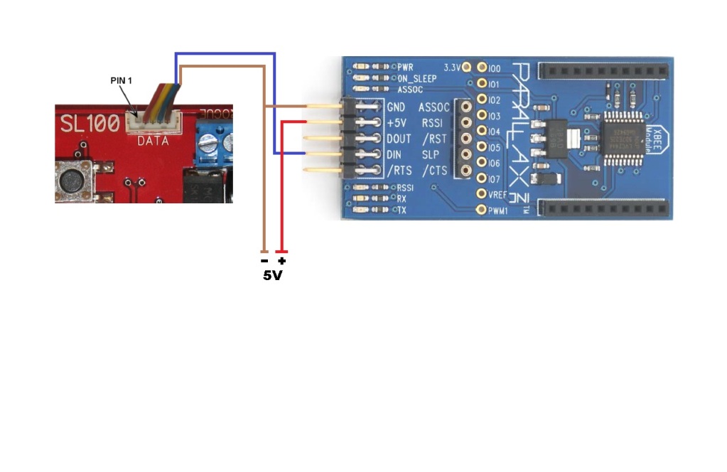
Here is a sketch on how do I plan to wire it together:

Do I have to power the SIP board with exactly 5 volts or can I power it with 6 volts, for example four 1,5V batteries. Am I in danger of frying up a voltage regulator?
Thanks for all your help.
Andrej Vrbec
This is my first post on this forum. I have a few questions I hope you can help me out with. I'm trying to build a telemetry system that will be used on board a high power rocket using XBee- PRO 868 radio modems. I already have an altimeter (Perfectflight Stratologger- http://www.perfectflite.com/sl100.html) that has a data port and outputs data signals at 3.3V CMOS logic level- 9600BPS, 8 data bits, no parity and 1 stop bit according to the manual. My plan is to use XBee-PRO 868 with Parallax USB adapter board for ground station and a XBee-PRO 868 with Parallax SIP adapter for flight unit. XBee-PRO 868 draws 500mA (and sometimes up to 800mA) while transmitting. While in flight it will be transmitting almost constantly. Question now is can the SIP adapter handle such a current draw? If it can't, can I use the XBee adapter bare board (http://www.parallax.com/Store/Accessories/CommunicationRF/tabid/161/CategoryID/36/List/0/SortField/0/Level/a/ProductID/642/Default.aspx)? In this case I would have to make my own power supply. How do you suggest I do that?
Here is a sketch on how do I plan to wire it together:

Do I have to power the SIP board with exactly 5 volts or can I power it with 6 volts, for example four 1,5V batteries. Am I in danger of frying up a voltage regulator?
Thanks for all your help.
Andrej Vrbec


Comments
I have a feeling I could have answered this off the top of my head two years ago, but I've lost it since. Oh, I now see in the schematic that the regulator used is an LM2937, and of course you can look that up and see that it only supplies 500 mA.
So I take it that we think his best solution will be to use something like that Sparkfun switching regulator to supply voltage to an XBee mounted on a standard board like this one:
http://www.parallax.com/Store/Accessories/CommunicationRF/tabid/161/CategoryID/36/List/0/SortField/0/catpageindex/2/Level/a/ProductID/642/Default.aspx
Then he can use the 6V input and also have enough current to work. RIght? Oops - wait. The Sparkfun product page says that switching power supply needs at least 8V input.
Andrej, I wonder if you might consider a different battery for your power supply. An 8.4V pack of some sort (from the RC hobbyists) might be a good choice.
Excellent. So his 6v input into that Sparkfun board into an XBee Pro 868 mounted on the simple adapter board (no regulator of its own) should work, I believe. I'll be interested in hearing his results.
Based on Mike's suggestions, I've purchased some copper tape to use as a shield. I'll give this a try once one of my battery powered wireless projects makes it back to a front burner.
I assume that Andrej will do quite a bit of ground testing before flying this thing, so interference problems should become apparent. Fortunately the Stratologger can be set to send out data for the radio to transmit even when it doesn't think it's flying, so it should be much easier than it used to be to ground test the RF link. Please let us know how the tape works when you get a chance.