Generating a 60Hz signal from Propeller chip
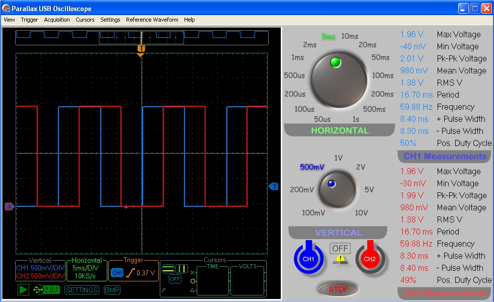
I am trying to generate two stable 60Hz signals shifted by 90 degrees to drive a clock device using the propeller chip. Using Timing.spin from OBEX, I can get close, but my clock is gaining ~5 minutes every 24 hours. Using an oscilloscope, I see my signal continuously drfts about +-1 Hz. See attached .spin sample. I am sure there must be a better, more accurate way of during this? Any suggestions welcomed.
Thanks.
Thanks.
spin

494B


Comments
John Abshier
http://forums.parallax.com/showthread.php?140813-clkfreq-cnt-confusion&p=1106211&viewfull=1#post1106211
CON

  _clkmode        = xtal1 + pll16x
  _xinfreq        = 6_250_000

  CHAN1           = 0
  CHAN2           = 1

PUB TimeBase | time, delay

  dira[CHAN1] := 1
  dira[CHAN2] := 1

  outa[CHAN1] := 0
  outa[CHAN2] := 0

  delay := clkfreq / 240
  time := cnt

  repeat
    waitcnt(time += delay)
    outa[CHAN1] := 1
    waitcnt(time += delay)
    outa[CHAN2] := 1
    waitcnt(time += delay)
    outa[CHAN1] := 0
    waitcnt(time += delay)
    outa[CHAN2] := 0
This still won't be 100% accurate, though, since 240 does not divide clkfreq evenly, but it should still give you results within the accuracy of your crystal. I got 60.00036 Hz with my Propeller when timed with an accurate frequency meter. That's 6ppm, or 1/2 second per day.
BTW, if your crystal is a little off, you can fudge the value of _xinfreq to obtain better accuracy. My nominal crystal frequency is 5 MHz. But when I changed _xinfreq to 5_000_030, I got a reading of 60.00000 Hz. Even then, however, I can count on frequency drift with temperature.
-Phil
On step at a time. The OP is just learning this stuff. Besides, getting two counters precisely phased with each other from Spin is no mean feat; and it's too soon to introduce PASM, methinks.
-Phil
Phill, your code did stabilize the frequency. I suspect that my clock will be more accurate tomorrow :-) To your point about accuracy, would a different external crystal (one that is evenly dividable by 240) yield better results? I am using my default 6.250 MHz crystal for testing purposes.
Greg
-Phil
Once you have the numbers defined then yes, a different frequency source will start to matter.
A 5ppm error is 13 seconds a month, if that is not 'close enough' you have some choices on what to do next.
Generic crystals spec in the region of 50ppm, but can be trimmed (as Phil did above) to give a single point calibrate, but that still leaves temperature drift and even aging.
A TXCO to 0.5ppm is possible, and that is roughly $5 (but hard to buy at 5-6MHz), or a GPS time code is perhaps the next step ?
<Warning snarky comment coming, NOT pointed at the OP!!>
Y'know, somewhere in that @#$@ poor documentation everyone was whining about in that other recent thread.
<End snarky comment>
But you don't absolutely need 5 to 6MHz, you can use the Xinput setting for _clkmode, and then feed DC through 80MHz in to Xin
True, but even there, there are fish hooks...
The Prop PLL is always x16 so wants 4..8MHz to be in spec, and TCXOs tend to be Clipped Sine out, and 12-26MHz
(some go to 10MHz, but the smaller ones are moving to 20.000 MHz )
So you could run in Xtal mode, and just run the Prop at 20MHz (certainly ok for 60Hz outputs!), but even here the prop data is vague on if the XIN or XOUT drives the internal clock buffer/schmitt in Xtal mode.
With a clipped sine of ~ 0.8V adding one inverter stage in the fastest mode, would be useful amplification.
A design could add a chip, like 74HC6323AD, to take the 20MHz clipped sine, to 5MHz square.
Actually, you wouldn't need 2 counters precisely set to output 60 Hz in quadrature.
I presume BonanzaMan only requires an "approximately" 90 degree quadrature drive for a mechanical 60 Hz clock motor.
He only needs to have a precision square wave from a single counter.
The 90 degree is obtained with a simple 4.2 mS RC delay for the other output.
Duane J
As each cog have two counters and even the Spin cog have the two counters unused ( I think), would not need to launch any extra cogs to get this done.
180deg would only require 1 counter (NCO differential), but 90deg would need both counters and you offset the start value of PHSA 90deg from PHSB's start value.