

VGA 256 Colors
 Roadster
Posts: 209
Roadster
Posts: 209
I have been working on getting more colors out of VGA and have been able to get 2 formats both only use passive components, more details to follow, I'm current working on a picture converter
I'm sorry about the bad photos, it's the best I can get with my camera.
RRRGGGBB
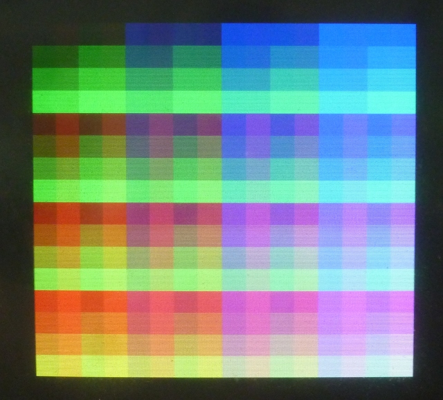
RRGGBBII

Demo_08_32x25x4bit_07_09_2012.zip
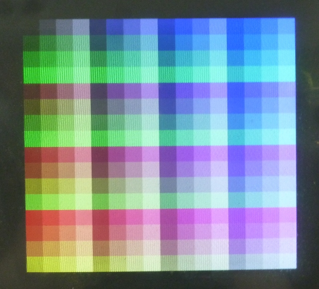
I'm sorry about the bad photos, it's the best I can get with my camera.
RRRGGGBB
RRGGBBII
Demo_08_32x25x4bit_07_09_2012.zip

640 x 577 - 205K
640 x 580 - 207K

Comments
-Phil
this is very nice especially rrggbii looks great...
Enjoy!
Mike
BTW do you mean RRGGBBII (missed a
Also anxiously await your hw details.
This is exciting, fantastic!
Who has not dreamed of doing something with the two lonely lost bits not used in the present VGA byte storage metaphor.?
Can't wait to see more ....
Perry
I guess you're doing some kind of compression to get that kind of resolution, right?
-Phil
The palette info takes some space too though, right?
I created the rrggbbii format because I was not happy with results I was getting with rrrgggbb, both formats are good it depends on what you want to do
rrggbbii is slightly better for photos
Are the palettes statically assigned in an 8x6 array or more dynamically. How do you (or your program) decide which colors to put in which palettes? Why the diodes instead of continuing the resistor-value progression? Show us some code already!
-Phil
Does each line have it's own palette? Or, every 8 pixels?
Don't see the reason for the diodes though. I think they are not necessary.
the Prop is forcing the voltage at these junctions where the diodes are.
The resistor values are the same for ii as each color, so the scheme has more redundancy than RRRGGGBB. The scheme prevents full saturation of each colour too, so I don't see how it can be superior - the color cube is not spanned effectively.
The resister arrangement you decide to use is up to you, I'm not saying what's right or wrong, I was merely trying different options and providing you with 8bit VGA palette
Demo_08_32x25x4bit_07_09_2012.zip
Without the diodes and continuing the binary weighting scheme for ii, here's the palette that results:
You do get good color saturation, but the fully-saturated colors are at only 80% of full intensity. By including the diodes, but reversed, you can get fully-saturated colors at full intensity, but with other tradeoffs.
-Phil
or does that kind of defeat the idea of using only the Prop Chip and a few discrete components?
Heresy! Heresy! (only joking)
-Phil
I was hoping at least something was still in production.
Hmm.. although the loop is 20 CLK, so that's only 4MHz pixel clock. Probably too low for a decent VGA resolution.
-Phil
All this RAMDAC discussion leaded me to an idea... The Amiga, or C64, or Atari ST, or Atari 800.. these computers was built with main processor, RAM and some custom chips. Graphic chip, sound chip, memory management chip, i/o chip...
so - let we make some customchips from Propellers...
A full Propeller with its 8 cogs and 32k RAM, dedicated as graphic custom chip, with defined pins, graphic modes etc...
Make a retrocomputer this way: define one Prop as a main CPU, next one as soundchip, one as graphic chip, one as MMU, make a standard computer structure with address and data buses, add 16 MB of RAM...
... yet another crazy idea...
but the Propeller as graphic custom chip can make a lot of good things, RAMDAC - like color translations included... We only have to feed it with data. Fast. This can be a problem.. but we all know there is nothing impossible with the Propeller, and even if it is, you can always add a second one.